Installation procedure – AEC TD Floor Mount Dryers User Manual
Page 10
OPERATING MANUAL - TD2 & TD4-25-100 DRYERS
Revision 8/31/01
Page 10
Electrical Connection:
Open electrical access door on the front of the machine by
turning the disconnect off and turning the lower clamping
screw 1/2 turn counterclockwise. Locate the disconnect by
following the operating handle down to the electrical panel.
Insert the incoming power cable or conduit through the hole
provided on the side of the machine.
« use approved wire and fastening means «
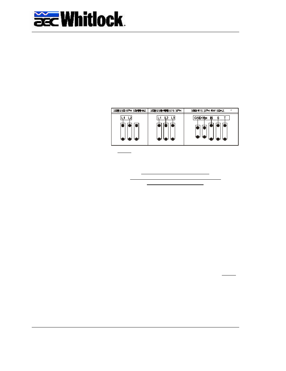
Wire incoming power to the top of the disconnect as shown in
the diagrams below.
NOTE:
When 3 wire supplies are used in place of 4 wire supplies,
a control transformer is required.
3 PHASE DRYER INSTALLATION
CHECK FOR CORRECT MOTOR ROTATION
BEFORE RUNNING DRYER
To check motor rotation.......
Leave the electrical cabinet door open so the blower can be
observed. Turn on the power to the dryer and press the
ON/
START touch pad and then immediately press the OFF/STOP
touch pad. Observe the cooling fan on the top of the blower
motor and verify the fan is turning clockwise. If the motor is
not turning clockwise, switch any two adjacent supply wires.
Compressed Air Connection:
Compressed air is only required for TD2 and TD4- 150/200/
300 Floor Mount models to operate the dryer’s Zone Valve.
For those units:
CONNECT COMPRESSED AIR TO INLET ON DRYER SIDE
PANEL. Maximum incoming pressure not to exceed 145 psi
(1.0 mpa). The pressure gauge on the dryer is factory set to
60 psi.
The unit is now ready for operation.
INSTALLATION
PROCEDURE
XX
XX