Mute control, Caution, Figure 2-8 — audio output wiring – Extron Electronics P-2 DA8 Series User Manual
Page 21
P/2 DA8 and P/2 DA12 • Installation and Operation
2-11
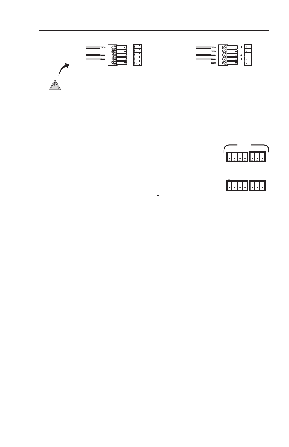
Unbalanced Stereo Output
Tip
NO GROUND HERE.
Sleeve(s)
Tip
NO GROUND HERE.
Balanced Stereo Output
Tip
Ring
Sleeve(s)
Tip
Ring
L
R
L
R
Left
Right
Left
Right
CAUTION
For unbalanced audio, connect the sleeve(s)
to the center contact ground.
DO NOT
connect
the sleeve(s) to the negative (-) contacts.
Figure 2-8 — Audio output wiring
Mute Control
The mute control provides a way to mute
individual outputs, or all outputs at once.
Audio and video for each output is muted
simultaneously.
Each output is assigned to a pin on the captive
screw connector. To mute any output, short
its pin to the ground pin ( ). Multiple outputs
can be shorted at the same time. To mute all outputs at once,
short pin A (all) to the ground pin.
The P/2 DA8 A model uses two 3.5 mm, 5-pole, captive screw
connectors. The P/2 DA12 A model (shown above) uses two
3.5 mm 4-pole connectors and two 3.5 mm 3-pole connectors.
For connections to captive screw receptacles, the length of the
exposed wires is critical.
N
The ideal length of stripped wire is 3/16” (5 mm):
If the stripped section of wire is longer than 3/16”,
•
the exposed wires may touch, causing a short circuit
between them.
If the stripped section of wire is shorter than 3/16”,
•
the wires can be easily pulled out even if tightly
fastened by the captive screws.
C
Do not tin the wires. Tinned wire does not hold its
shape and can become loose over time.
2 4 6
8 10 12
1
A
3 5
7 9 11
MUTE