Audio input, Audio output, Installation and operation, cont’d – Extron Electronics P-2 DA8 Series User Manual
Page 20: Figure 2-6 — audio input, Figure 2-7 — audio output connections, Sleeve ( ) ring (r) tip (l)
P/2 DA8 and P/2 DA12 • Installation and Operation
Installation and Operation, cont’d
2-10
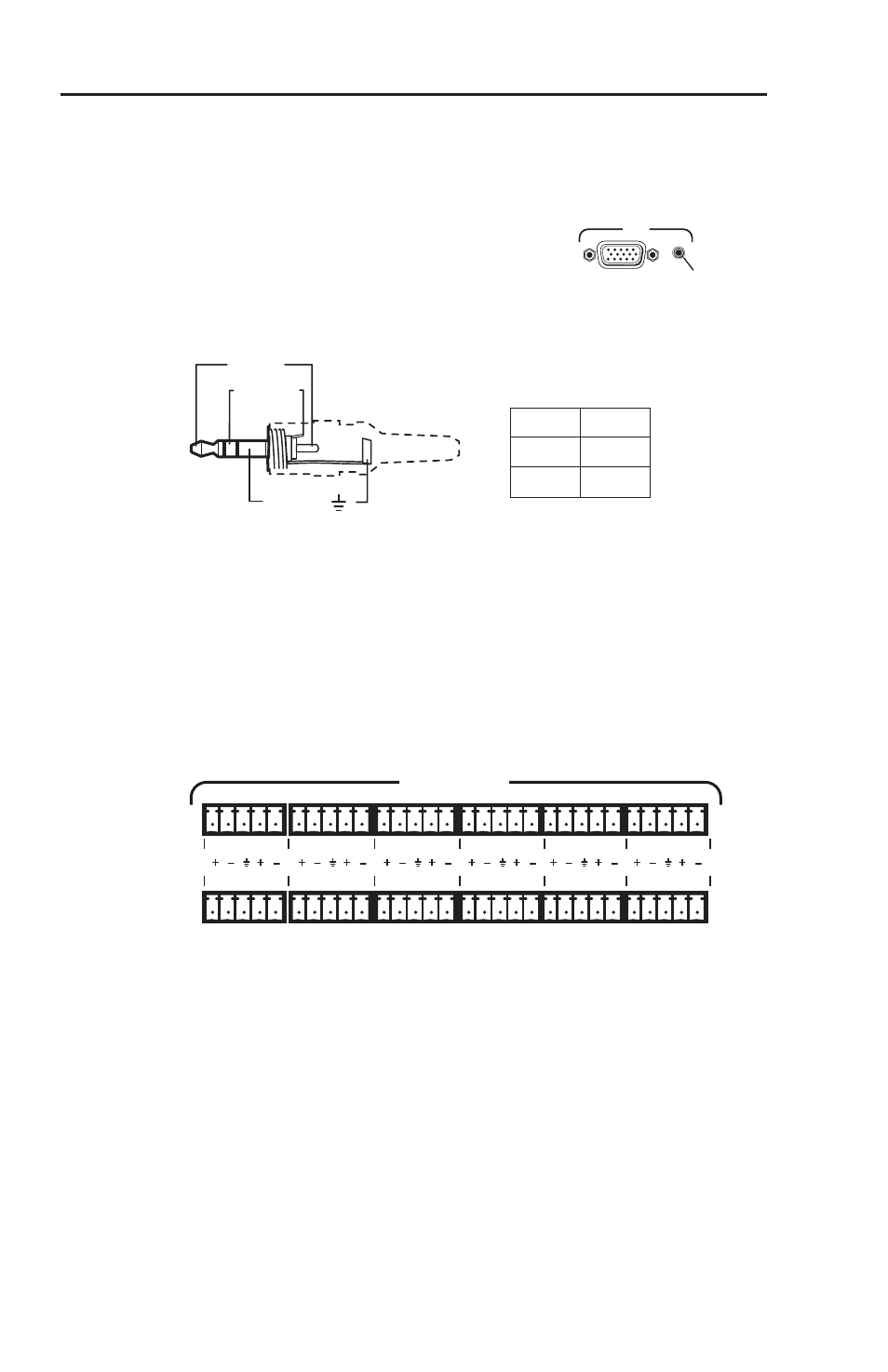
Audio input
For models P/2 DA8 A and P/2 DA12 A, use a female 3.5 mm
mini Tip Ring Sleeve (TRS) connector to provide an unbalanced
audio input. Switch off power to the distribution amplifier and
audio source. Connect the audio source
to the audio input socket on the rear
panel of the distribution amplifier.
Wiring for the TRS connector is shown in the figure below.
Sleeve ( )
Ring (R)
Tip (L)
3.5 mm Stereo Plug Connector
(unbalanced)
Tip
Ring
Sleeve
Left +
Right +
Ground
Figure 2-6 — Audio input
Audio output
The P/2 DA8 A (eight outputs) and P/2 DA12 A (twelve
outputs) use 3.5 mm, 5-pole, captive screw connectors for audio
outputs as shown in figure 2-7.
L
2
R
L
1
R
L
4
R
L
3
R
L
6
R
L
5
R
L
8
R
L
7
R
L
10
R
L
9
R
L
12
R
L
11
R
AUDIO OUTPUTS
Figure 2-7 — Audio output connections
The audio outputs can be balanced or unbalanced depending
on the wiring (see figure 2-8 on the next page). The length of
exposed wires in the captive screw connector is critical (see the
note and caution on the next page).
N
Balanced output wiring produces a +6 dB gain.
Unbalanced output wiring produces 0 dB gain.
INPUT
Audio Input