Rear panel features, Figure 2-4 — rear panel features – Extron Electronics P-2 DA8 Series User Manual
Page 17
P/2 DA8 and P/2 DA12 • Installation and Operation
2-7
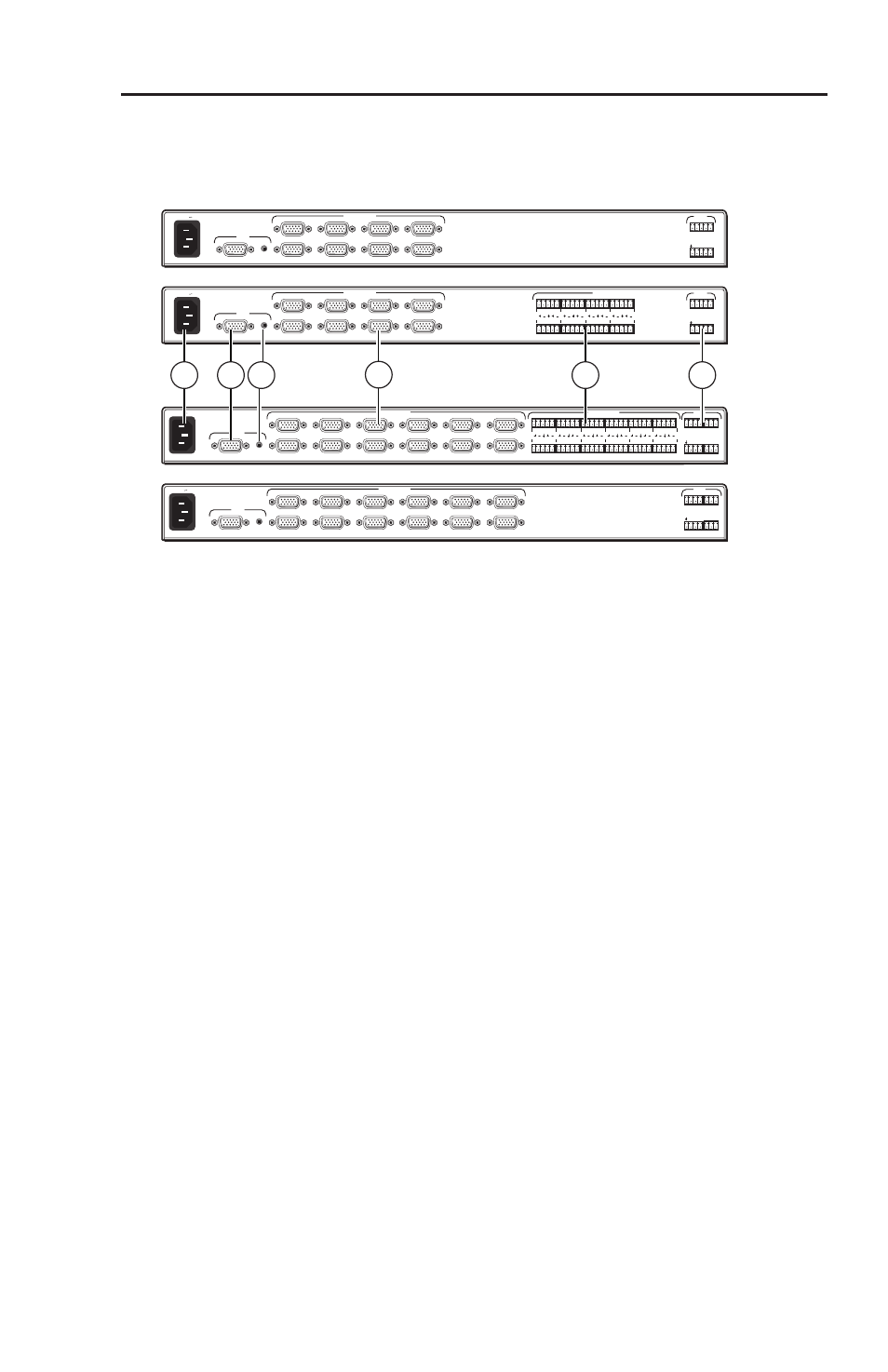
Rear Panel Features
All power, input and output connections are located on the rear
panels of all models, as shown in the figure below.
L
2
R
L
1
R
L
4
R
L
3
R
L
6
R
L
5
R
L
8
R
L
7
R
2 4 6
8
1
A
3 5
7
8
7
6
5
4
3
2
INPUT
VIDEO OUTPUTS
AUDIO OUTPUTS
MUTE
1
50/60 Hz
100-240V 0.3A
L
2
12
R
L
1
R
L
4
R
L
3
R
L
6
R
L
5
R
L
8
R
L
7
R
L
10
R
L
9
R
L
12
2 4 6
8 10 12
1
A
3 5
7 9 11
R
L
11
R
11
10
9
8
7
6
5
4
3
2
INPUT
VIDEO OUTPUTS
AUDIO OUTPUTS
MUTE
1
50/60 Hz
100-240V 0.3A
3
8
7
5
6
4
2 4 6
8
1
A
3 5
7
8
7
6
5
4
3
2
INPUT
VIDEO OUTPUTS
MUTE
1
50/60 Hz
100-240V 0.3A
12
2 4 6
8 10 12
1
A
3 5
7 9 11
11
10
9
8
7
6
5
4
3
2
INPUT
VIDEO OUTPUTS
MUTE
1
50/60 Hz
100-240V 0.3A
P/2 DA8
P/2 DA12
P/2 DA8 A
P/2 DA12 A
Figure 2-4 — Rear panel features
c
AC power connection — Use the provided IEC connector to
connect the unit to a convenient power socket. The internal
power supply will support 100-240 VAC, 50-60 Hz.
d
Video input — One female DB-15 connector is used for video
input. Acceptable input formats include: RGBHV, RGBS,
RGsB, RsGsBs, YUV (tri-level and bi-level sync), S-video, and
composite video. (See page 2-9.)
e
Audio input (P/2 DA8 A and P/2 DA12 A models only) — One
female 3.5 mm TRS connector accepts unbalanced audio input.
(See page 2-10.)
f
Video outputs — Up to eight (P/2 DA8 series) or twelve (P/2
DA12 series) outputs can be connected using female DB-15
connectors. The output signal format follows that of the input.
(See page 2-9.)
N
ID bits on pins 4, 11, 12, and 15 are routed to Output 1.
g
Audio outputs (P/2 DA8 A and P/2 DA12 A models only)
—
Up to eight (P/2 DA8 A) or twelve (P/2 DA12 A) outputs
can be connected using 3.5 mm 5 pole captive screw connectors.
Outputs can be balanced or unbalanced. (See page 2-10.)
h
Mute controls — On P/2 DA 8 models, two 3.5 mm, 5-pole
captive screw connectors will be used to mute video and audio
from specific or all outputs. On P/2 DA12 models, two 3.5 mm,
4 pole and two 3.5 mm, 3 pole captive screw connectors will be
used. (See page 2-11.)