Switch settings md-54, Warning! do not open connected unit, Function switch 1 – Westermo MD-54 User Manual
Page 3: Function switch 2, Function switch 2 factory settings
14
6605-2001
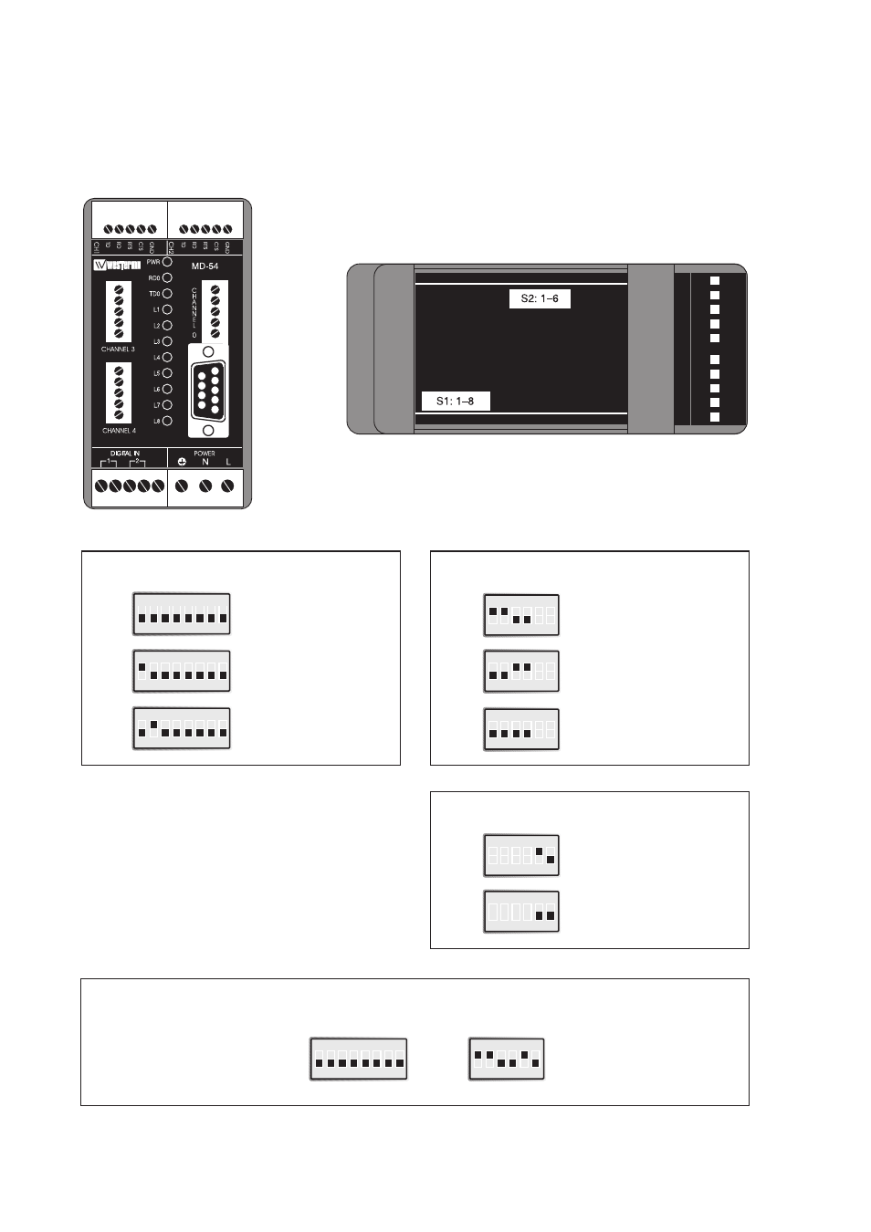
Switch settings MD-54
The MD-54 can be set for a range of different operating conditions. Some settings are
made via DIP-switches located under the lid on the top of the unit.
ON
1 2 3 4 5 6 7 8
ON
1 2 3 4 5 6
5
4
3
2
1
5
4
3
2
1
1
2
3
4
5
1234
5
1
2
3
45
Warning! Do not open
connected unit
Function switch 1
Normal function
S1
ON
1 2 3 4 5 6 7 8
New program can
be downloaded
via channel 0 *
S1
ON
1 2 3 4 5 6 7 8
Settings can be made
via channel 0 **
S1
Function switch 2
Termination 4-wire (RS-422)
S2
ON
1 2 3 4 5 6
Termination 2-wire (RS-485)
S2
ON
1 2 3 4 5 6
No termination
S2
ON
1 2 3 4 5 6
Function switch 2
Factory settings
4-wire (RS-422)
S2
ON
1 2 3 4 5 6 7 8
S1
ON
1 2 3 4 5 6
S2
ON
1 2 3 4 5 6
2-wire (RS-485)
S2
*) The unit will automatically adapt its communication
parameters for channel 0.
PC based software from Westermo is required to down-
load a new program.
**) In this setting channel 0 communicates as follow:
– 9 600 bit/s
– 8 bits wordlength
– no parity
– 1 stop bit