3 communications, The lr-11 routes lontalk, Lr-11 lr-11pp – Westermo LR-11 User Manual
Page 7: Figure 3.2 general data flow, Orks, Rx1 tx1 rx2 tx2 rx tx
7
6608-2211
3 COMMUNICATIONS
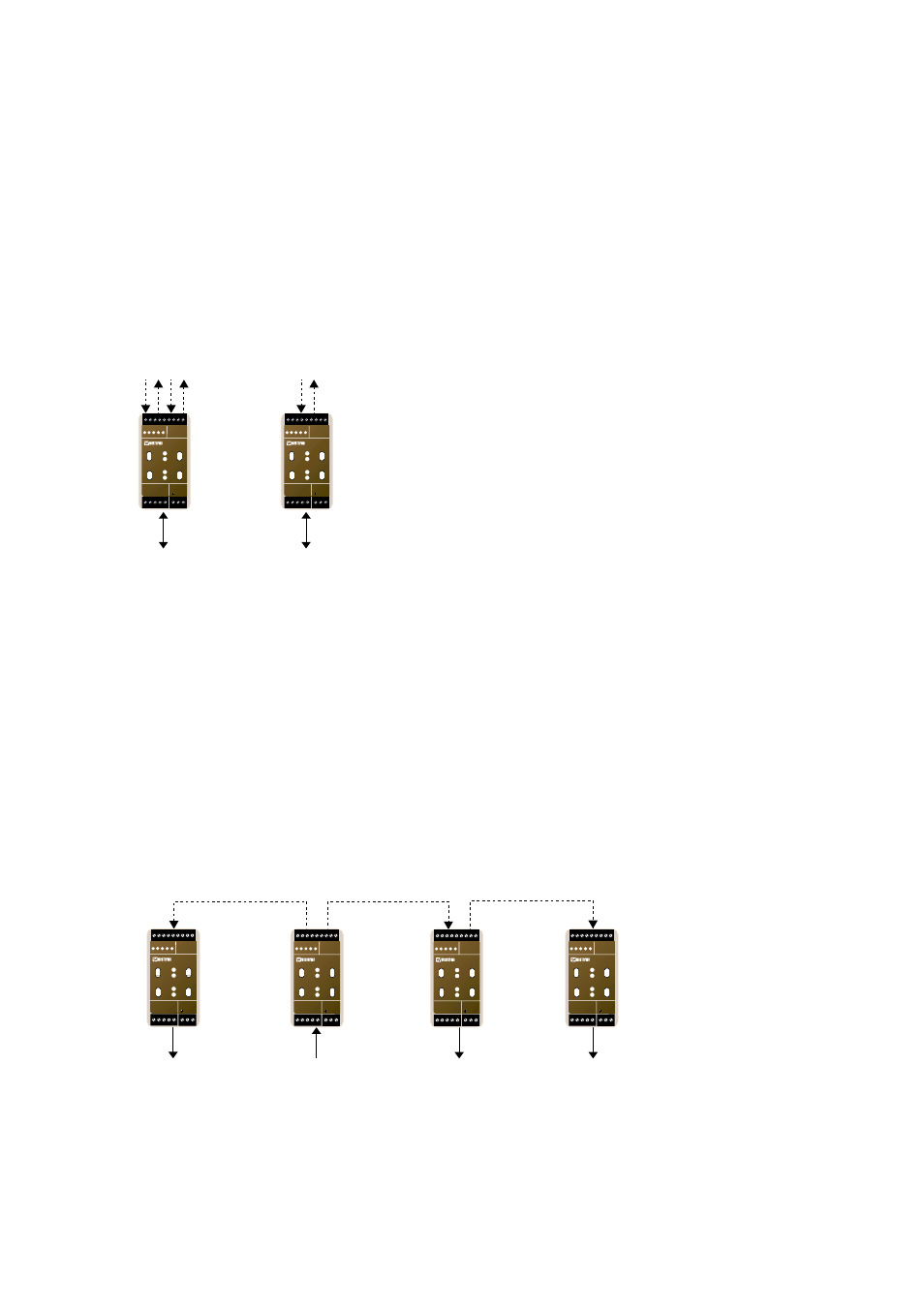
The LR-11 routes LonTalk
®
packets between a TP/FT-10 channel and fibre optic channel.
The communication channels consists of a fibre optic interface and a TP/FT-10 interface.
The fibre optic interface is equipped with either one (PP-version) or two sets of fibre
optic ports, each with its separate transmitter and receiver, and the TP/FT-10 channel
consists of one L
ON
W
ORKS
®
FTT-10A transceiver. Figure 3.1 illustrates the communica-
tion ports on the LR-11.
If there are only two network segments that are to be connected, the point to point
version of LR-11 could be used. If the network contains of more than two segments, the
data needs to be retransmitted onto the fibre link to other connected network segment.
The LR-11 with its two sets of fibre optic ports can then be used to build bus or ring
topology fibre links.
Figure 3.2 illustrates the general data flow when data is received and routed to the fibre
side from a TP segment.
Figure 3.1 Ports on LR-11 and LR-11 PP (point to point)
Fibre Optic
TP Network
TP Network
Rx1
Tx1
Rx2
Tx2
Rx
Tx
LR-11
LR-11PP
N1 N2
L
N
LR-11
LONWORKS TP/FT-10
POWER
Rx1
Rx2
Tx1
Tx2
TD RD ASRV BSRV
C
E
PWR
OPTO LINK MONITOR
CH1
C
E
CH2
N1 N2
L
N
LR-11
LONWORKS TP/FT-10
POWER
Rx1
Rx2
Tx1
Tx2
TD RD ASRV BSRV
C
E
PWR
OPTO LINK MONITOR
CH1
C
E
CH2
Fibre
From TP Network
To TP Network
LR-11
LR-11
LR-11
To TP Network
LR-11
To TP Network
N1 N2
L
N
LR-11
LONWORKS TP/FT-10
POWER
Rx1
Rx2
Tx1
Tx2
TD RD ASRV BSRV
C
E
PWR
OPTO LINK MONITOR
CH1
C
E
CH2
N1 N2
L
N
LR-11
LONWORKS TP/FT-10
POWER
Rx1
Rx2
Tx1
Tx2
TD RD ASRV BSRV
C
E
PWR
OPTO LINK MONITOR
CH1
C
E
CH2
N1 N2
L
N
LR-11
LONWORKS TP/FT-10
POWER
Rx1
Rx2
Tx1
Tx2
TD RD ASRV BSRV
C
E
PWR
OPTO LINK MONITOR
CH1
C
E
CH2
N1 N2
L
N
LR-11
LONWORKS TP/FT-10
POWER
Rx1
Rx2
Tx1
Tx2
TD RD ASRV BSRV
C
E
PWR
OPTO LINK MONITOR
CH1
C
E
CH2
Figure 3.2 General data flow