Westermo LR-11 User Manual
Page 10
10
6608-2211
3.3.1 Alarm indications
The LR-11 unit has two alarm outputs marked as CH1 and CH2. When a unit detects a
fault on a fibre optic link the circuit between contacts “C” and “E” is opened. See sec-
tion 6.2 and 6.3 for an example how to connect the alarm output to an external relay.
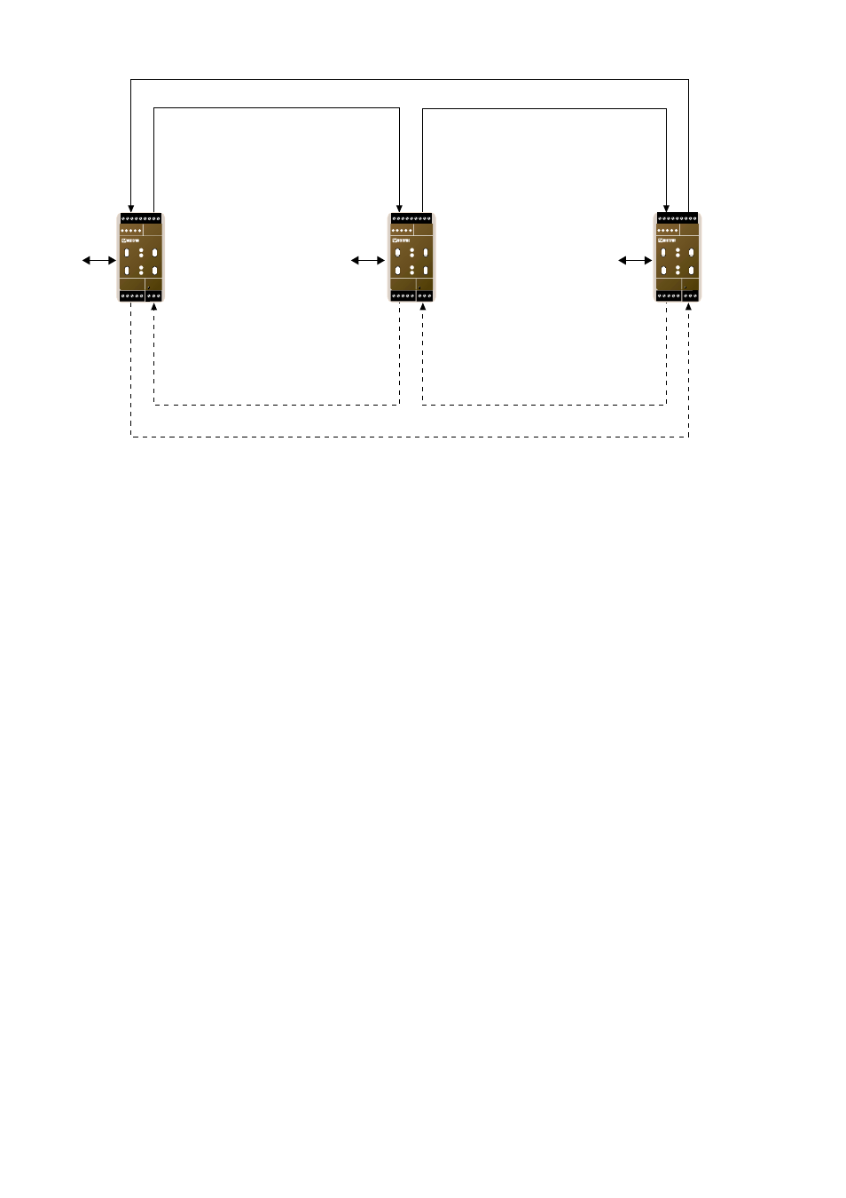
In case of a fault on a fibre link, the receiver on the closest downstream unit will detect
the fault and assert a receive failure alarm. The ring master will also be aware of the fault
and assert the link failure alarm corresponding to the faulty fibre link. In that way a mon-
itoring system only needs to monitor the ring master to obtain the over-all status of the
two fibre links. To find which segment that is broken the alarm status on each unit must
be investigated.
Figure 3.5 schematically illustrates how the fibre links are connected to form two rings.
Rx2
TP Network
TP Network
TP Network
Tx1
Rx2
Tx1
Rx2
Tx1
Tx2
Rx1
Tx2
Rx1
Tx2
Rx1
LR-11
LR-11 Ringmaster
LR-11
N1 N2
L
N
LR-11
LONWORKS TP/FT-10
POWER
Rx1
Rx2
Tx1
Tx2
TD RD ASRV BSRV
C
E
PWR
OPTO LINK MONITOR
CH1
C
E
CH2
N1 N2
L
N
LR-11
LONWORKS TP/FT-10
POWER
Rx1
Rx2
Tx1
Tx2
TD RD ASRV BSRV
C
E
PWR
OPTO LINK MONITOR
CH1
C
E
CH2
N1 N2
L
N
LR-11
LONWORKS TP/FT-10
POWER
Rx1
Rx2
Tx1
Tx2
TD RD ASRV BSRV
C
E
PWR
OPTO LINK MONITOR
CH1
C
E
CH2