Connections, Dsl screw connector 1 & 2, Ethernet tx connection (rj-45 connector) 1 – 4 – Westermo DDW-221 User Manual
Page 11: Power connection
11
6642-22102
II 3G EEx nA II T4
* Direction relative this unit
** To minimise the risk of interference, a shielded cable is recommended when the cable is located inside 3 m
boundary to the rails and connected to this port. The cable shield should be properly connected (360°) to an
earthing point within 1 m from this port. This earthing point should have a low impedance connection to the con-
ductive enclosure of the apparatus cabinet, or similar, where the unit is built-in. This conductive enclosure should
be connected to the earthing system of an installation and may be directly connected to the protective earth.
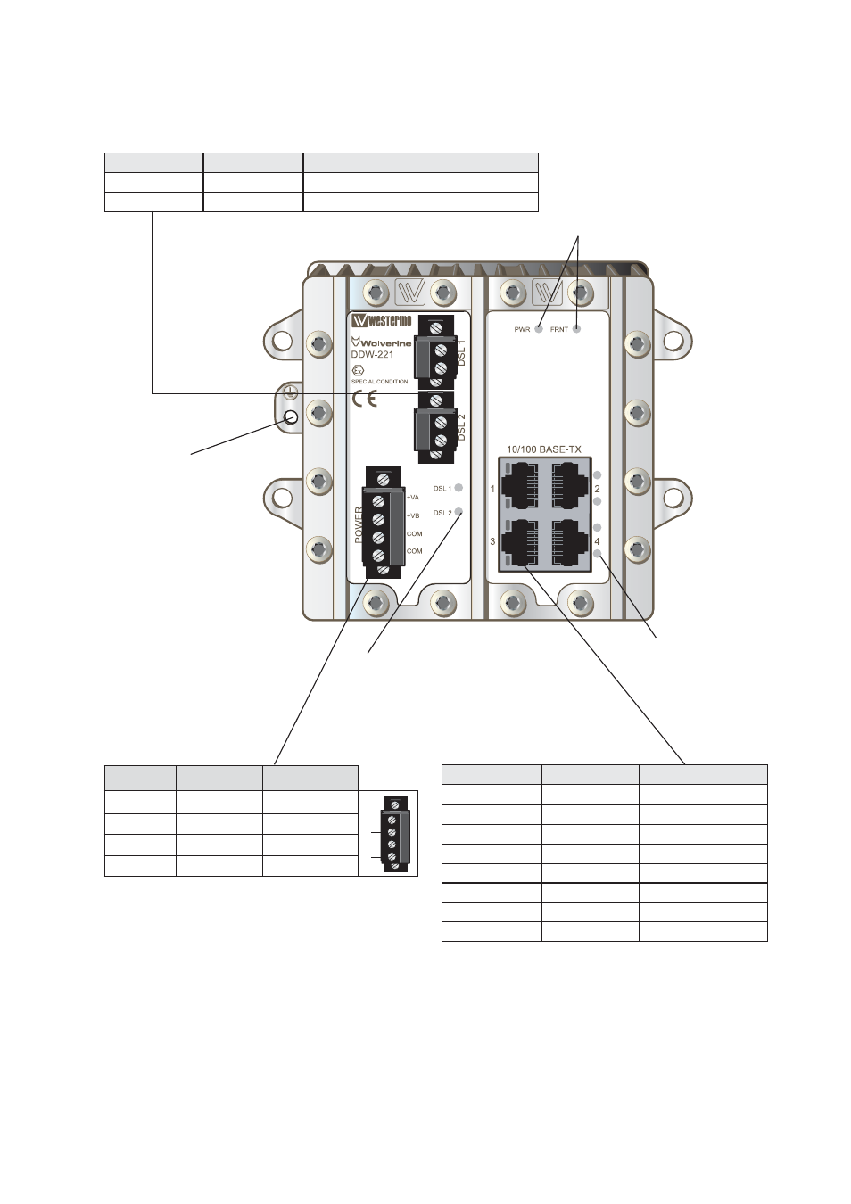
Connections
DSL screw connector 1 & 2
Position
Direction Description
1
In/Out
2-wire Receive/ Transmit SHDSL
2
In/Out
2-wire Receive/ Transmit SHDSL
Ethernet TX connection
(RJ-45 connector) 1 – 4**
Position
Direction*
Description
1
In/Out
TD+
2
In/Out
TD–
3
In/Out
RD+
4
–
Not Connected
5
–
Not Connected
6
In/Out
RD–
7
–
Not Connected
8
–
Not Connected
CAT 5 cable is recommended.
Unshielded (UTP) or shielded (STP) connectors
can be used.
LED indicators
(for details see next page)
LED indicators, also
integrated in RJ-45 connector.
(for details see next page)
LED indicators
(for details see next page)
Earth connect
Power connection
Position
Direction*
Description
1
In
+ Voltage A
2
In
+ Voltage B
3
In
Common
4
In
Common
1
2
3
4