Controller overview, Vavbox controller 3 technical guide features, Vavbox controller – WattMaster VAVBOX User Manual
Page 3: Oe322 output expansion board, Figure 1: vavbox controller dimensions
VAVBOX Controller
3
Technical Guide
Features
VAVBOX Controller
This manual applies to the VAVBOX controller that is included in the
following WattMaster products:
MG742-VAV
Pressure Dependent VAVBOX Kit For
Terminal Units w/o Fan Electric or Hot
Water Heat
MG744-VAV
Pressure Independent VAVBOX Kit For
Terminal Units w/o Fan Electric or Hot
Water Heat
MG742-03-VAV
Pressure Dependent VAVBOX Kit For
Terminal Units or Fan Terminal Units
With Electric or Hot Water Heat
MG744-03-VAV
Pressure Independent VAVBOX Kit For
Terminal Units or Fan Terminal Units
With Electric or Hot Water Heat
The VAVBOX Controller is used for controlling airflow and operation
of VAV terminal units. It is a programmable digital controller, which
allows for program setpoints to be stored in non-volatile memory. The
controller is connected to a room sensor which monitors space tem-
perature allowing the VAVBOX controller to modulate a damper in re-
sponse to space temperature, duct temperature and airflow requirements
in the controlled space.
The VAVBOX controller has three integral modular jacks for connec-
tion to the actuator, airflow sensor (for pressure independent applica-
tions), and relay or analog expansion boards, via modular cables. The
controller has an on-board dip switch provided for board addressing.
Controller Overview
The VAVBOX controller is provided with two relays for tri-state con-
trol of the damper actuator. All outputs and the relay common are elec-
trically isolated from all other circuitry on the board. All relay outputs
are supplied with transient suppression devices across each set of con-
tacts to reduce EMI and arcing. The relay output contacts are rated for
pilot duty control of a maximum of 2 Amps @ 24 VAC or 24 VDC.
The actuator connects via a modular cable to the board and provides the
VAVBOX controller with feedback monitoring for precise positioning
of the actuator.
OE322 Output Expansion Board
The OE322, 3 Relay with Analog Output Expansion board is used in
conjunction with the VAVBOX Controller board to allow for control
of VAV terminal units, including series and parallel fan terminal units
with up to 2 stages of electric heat or modulating hot water heat. The
OE322, 3 Relay with Analog Output Expansion board provides 3
relay outputs for pilot duty switching control, and 1 Analog output for
control of a 0-10 V modulating hot water valve.
The OE322 Output Expansion board connects to the VAVBOX
controller board by means of a modular cable provided with the
expansion board. Power is supplied to the board by means of this
modular cable. Screw terminals are provided for connection of field
wiring to the relay and analog outputs.
The relay outputs are N.O. contacts with one common terminal. All
outputs and the relay common are electrically isolated from all other
circuitry on the board. All relay outputs are supplied with transient
suppression devices across each set of contacts to reduce EMI and
arcing. The relay output contacts are rated for pilot duty control of a
maximum of 2 Amps @ 24 VAC or 24 VDC. The analog output provides
a 0 – 10 VDC modulating signal output into a 1K ohm minimum load.
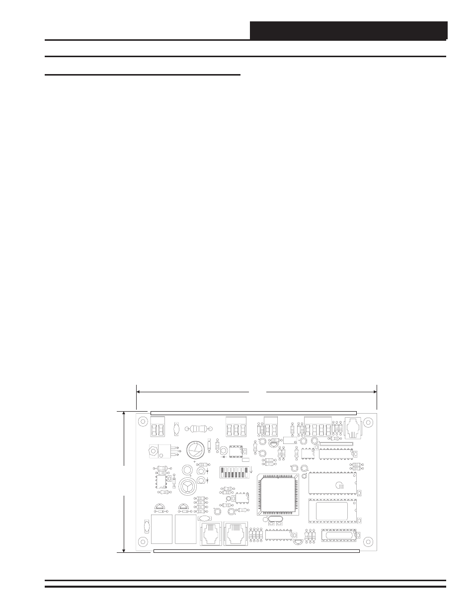
Figure 1: VAVBOX Controller Dimensions
7.00"
4.00”
CX6
SW1
U10
75176
EXPANSION
Q3
Q2
D3
VR1
7824
GND
GND
GND
AUX2
AUX1
AUX
+VS
TMP
24V
AC
R17
R16
U7
C7
R15
POWER
R21
R35
YS101562
REV3
D4
R26
LD3
L1
SCAN
REC
R12
C6
R11
TOKEN
NET
LD2
32
R14
R13
R100
LD1
C5
D1
K1
V2
V3
K2
D2
ACTUATOR
R10
R9
PJ2
V1
C4
EPROM
VREF
ADJ
R23
C10
EWDOG
COMM
D7
CX10
R25
R28
T'S
TAT
U11
C15
R20
C11
R24
8
16
2
4
ADDRESS
ADD
1
U6
U5
R19
U9
CX9
R32
D5
C14
P.U.
R22
C13
R27
D5
RAM
C9
C8
CX5
PJ1
C3
R8
R7
R5
R6
R4
C2
C1
X1
U2
R1
R2
R3
CX2
Q1
16L8
R34
FLOW
U8
1
RN1
CX8
U4
R18
CX4
U3
CX3
U1
PAL
CX1