Start-up & commissioning, Vavbox controller technical guide 11, Power wiring – WattMaster VAVBOX User Manual
Page 11: Initialization, Add sw1
VAVBOX Controller
Technical Guide
11
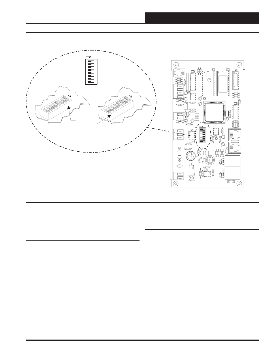
Figure 9: Address Switch Setting
VAVBOX Controller Board
16
32
NET
TOKEN
8
4
2
1
Address Switch Shown Is
Set For Address 9
Address Switch Shown Is
Set For Address 13
Controller
Address Switch
ADD
SW1
1
1
2
2
4
4
8
8
16
16
32
32
TO
KEN
TOKEN
NET
NET
ADD
ADD
The Address For Each Controller
Must Be Between 1 And 58 And Be
Unique To The Other Controllers
On The Local Loop
CX6
SW1
U10
75176
EXP
ANSION
Q3
Q2
D3
VR1
7824
GND
R
SHLD
GND
GND
AUX2
AUX1
AUX
+VS
TMP
T
24VAC
R17
R16
U7
C7
R15
POWER
R21
R35
YS101
562
REV
3
D4
R26
LD3
L1
SCAN REC
R12
C6
R1
1
TOKEN
NET
LD2
32
R14
R13
R100
LD1
C5
D1
K1
V2
V3
K2
D2
ACTUA
TO
R
R10
R9
PJ2
V1
C4
EPROM
VREF
ADJ
R23
C10
EWDOG
COMM
D7
CX10
R25
R28
T'STAT
U1
1
C15
R20
C1
1
R24
8
16
2
4
ADDRESS
ADD
1
U6
U5
R19
U9
CX9
R32
D5
C14
P.U.
R22
C13
R27
D5
RAM
C9
C8
80C55
2
CX5
PJ1
C3
R8
R7
R5
R6
R4
C2
C1
X1
U2
R1
R2
R3
CX2
Q1
16L8
R34
FLOW
U8
1
RN1
CX8
U4
R18
CX4
U3
CX3
U1
PA
L
CX1
For detailed information regarding communication wiring and connec-
tion for Interconnected and Networked systems, please see the Watt-
Master WMVAV System Installation & Troubleshooting Guide.
Power Wiring
One of the most important checks to make before powering up the sys-
tem for the first time, is to confirm proper voltage and transformer
sizing for the VAVBOX boards that are connected to it. Each VAVBOX
controller requires 6 VA of power delivered to it at 24 VAC. See page
7 of this manual for complete wiring and transformer sizing informa-
tion for the VAVBOX controller.
Check all connections to be sure they are tight with no loose wire starnds
hanging loose. Confirm that all sensors required for your system are
mounted in the appropriate location and wired correctly to the VAVBOX
controller. Check the actuator cable and be sure it is plugged in and
secured to the modular connector on the actuator and the VAVBOX
controller board modular connector. Be sure any expansion boards con-
nected to the VAVBOX controller are also correctly wired per the ex-
pansion board wiring instructions on pages 8 through 102 of this manual.
After all the above wiring checks are complete, apply power to the first
VAVBOX on the loop, that is connected to the WMVAV controller.
Initialization
Upon applying power to the VAVBOX controller the following should
occur:
On system power-up, the SCAN LED is extinguished for a few seconds
and then the controller “flashes” its address switch setting. If the ad-
dress switch were set to 7, you would see 7 flashes. After the address is
finished, the LED will extinguish for another 5 seconds. At the conclu-
sion of this 5-second delay, the LED will begin a continuous flashing
while the Damper Feedback limits are calibrated. If the Damper is driv-
ing open, the LED will blink slowly. If the Damper is driving closed,
the LED will blink fast. When the calibration is completed, the normal
diagnostic flashes will commence. These diagnostic flashes are described
later in this document. In addition, during the first few seconds of power-
up, all default setpoints are initialized and all outputs are turned off.
a 30 second start-up delay to protect the fan and other components
from short cycling during intermittent power conditions. If all inputs
are operating correctly it will blink once every ten seconds.
Start-up & Commissioning