Rs-485 communications, Mcd troubleshooting with a digital voltmeter – WattMaster WCC III part 10 User Manual
Page 11
10. RS-485 COMMUNICATIONS
WCC III Technical Guide
10-9
MCD Troubleshooting with a Digital Voltmeter
Troubleshooting of the WCC III system RS-485 satellite communications loop is possible with a digital voltmeter.
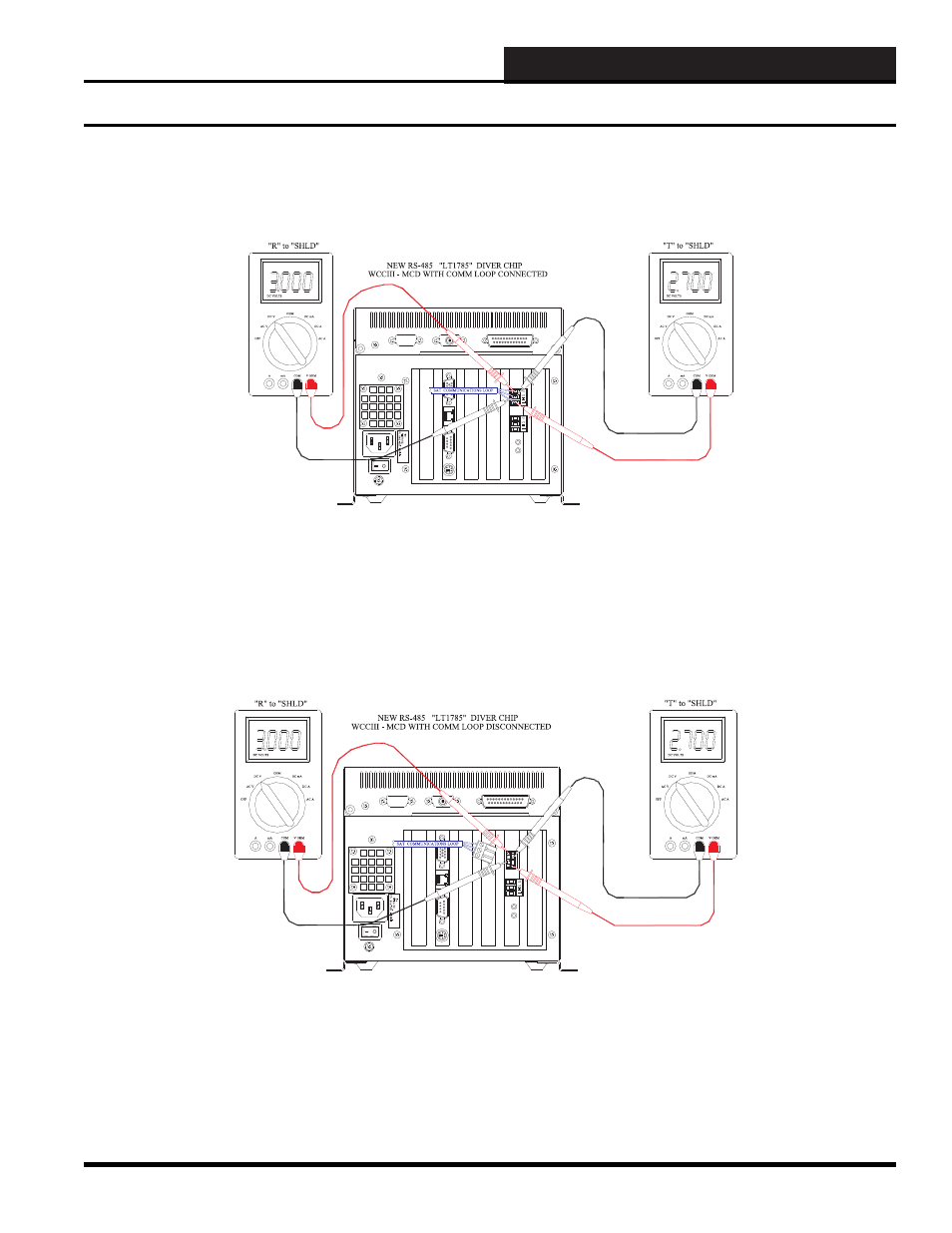
Figure 10-7: Typical WCC III - MCD RS-485 Satellite Communications DC Voltage Measurements with the Loop
Connected
Figure 10-8: Typical WCC III - MCD RS-485 Satellite Communications DC Voltage Measurements with the Loop
Disconnected
The voltage measurements in Figure 10-7 are approximate voltages. These voltage measurements are taken when the power to the
WCC III - MCD is “ON” and the RS-485 communications loop is connected. These two voltages will fl uctuate slightly and also will
momentarily “fl ip” to the other meter reading’s value. The voltage measurement from “T” to “SHIELD” should be around 2.7 VDC. The
voltage measurement from “R” to “SHIELD” should be around 3.00 VDC. Typical bad voltage measurement values would be anything
above 3.8 VDC and anything below 1.5 VDC. This voltage measurement applies to both top and bottom RS-485 loop communications
connections.
The voltage measurements in Figure 10-8 are approximate voltages. These voltage measurements are taken when the power to the
WCC III - MCD is “ON” and the RS-485 communications loop is disconnected. These two voltages will fl uctuate slightly and also will
momentarily “fl ip” to the other meter reading’s value. The voltage measurement from “T” to “SHIELD” should be around 2.7 VDC. The
voltage measurement from “R” to “SHIELD” should be around 3.00 VDC. Typical bad voltage measurement values would be anything
above 3.8 VDC and anything below 1.5 VDC. This voltage measurement applies to both top and bottom RS-485 loop communications
connections.
MCD Communications Troubleshooting with a Digital Voltmeter