Instruction handbook – Watson-Marlow PD12I User Manual
Page 6
INSTRUCTION HANDBOOK
PD12I / PD12P
PD12IP IH 1.03 EN
Version: 1.03
Page 6 of 20
3.3 Installation
3.3.1 PD12I Installation
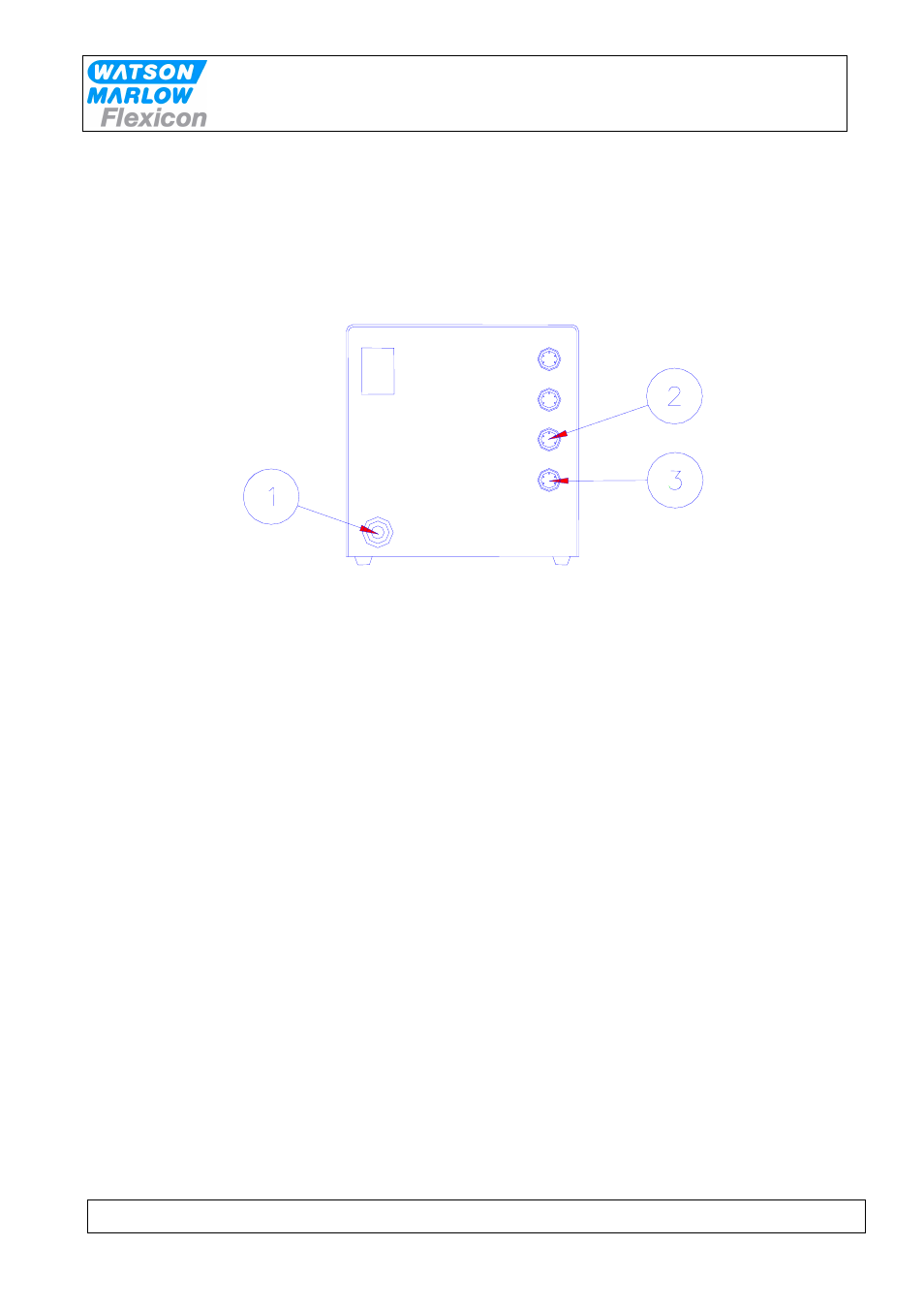
PD12I must be placed on a stable bedplate, and all electrical connections are on its rear.
Fig. 3.1
The cable with plug (1) is connected to an earthed switch.
The communication cable from MC12 (type 3) comes fitted with two 4-pin DIN plugs. One is
connected to the "net 1" socket (2) on the PD12I, and the other plug is connected to the "net"
socket on MC12.
The terminator supplied with MC12 (4-pin blind DIN plug) is connected to the "net 2" (3)
socket on PD12I.
Should the system be operating more than one PD12I, the "net 2" socket (3) is to be
connected to the "net 1" socket (2) on the next PD12I by a communication cable (type 3).
The terminator is connected to the last PD12I on the line.
Address "1" is the factory setting of PD12I. In case you want to change this setting, please
consult section 3.4 in this manual.
PD12I is now ready to be switched on and to be programmed from the MC12.