Operators manual, Gd30i, 8 interface and change of power – Watson-Marlow GD30I User Manual
Page 13
OPERATORS MANUAL
Machine Type:
GD30I
GD30I OM 1.01 EN
Ver 1.01
Date 24-08-2006
Page 13 of 15
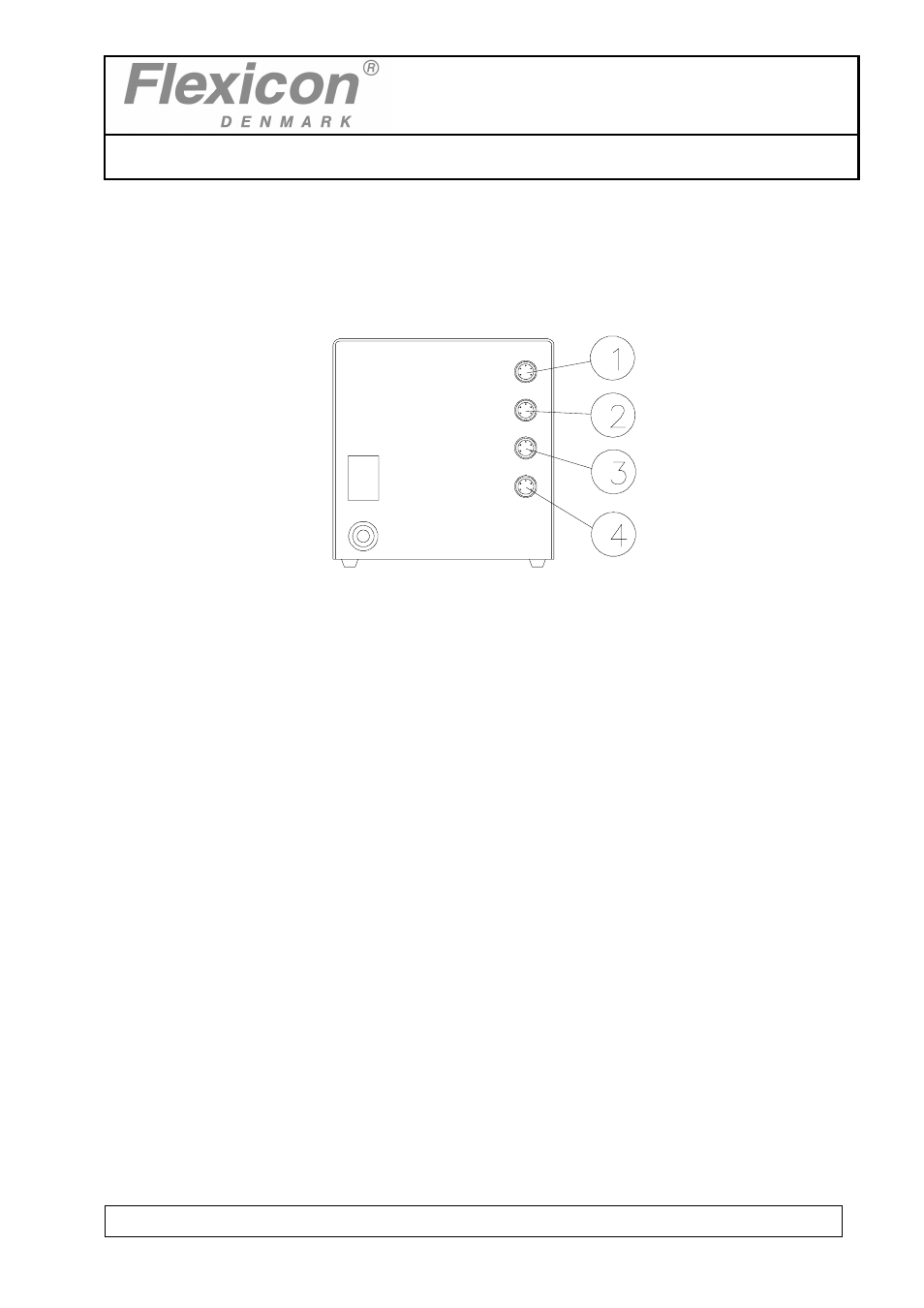
8 INTERFACE AND CHANGE OF POWER
8.1 Interface
Fig. 8.1
(1) external 1: pin 1: Input for start signal.
+5 - 50 VDC, min. 100 msec. positive-edge-trigged.
pin 2: Output, +24 VDC, max. 500 mA.
pin
3:
Ground.
pin 4: Status output, max. +24 VDC, 100 mA.
Pin 4 is earthed via an open collector during filling.
Pin 5: Status output, max. +24VDC, 100 mA
Pin 5 is complementary to pin 4.
(2) external 2: pin 1: Input for disabling.
+5 to +50 VDC. If this pin is activated, the drive will be
disabled
(no
dispensing).
pin 2: Output, +24 VDC, max. 500 mA.
pin
3:
Ground.
pin 4: Status output, max. +24 VDC, 100 mA.
Pin 4 is grounded via an open collector during filling.
pin 5: Status output, max. + 24 VDC, 100 mA.
Pin 5 is complementary to pin 4.
- 323Dz (53 pages)
- 620SN (100 pages)
- Bredel 25 (76 pages)
- APEX35 (72 pages)
- Bredel 80 (76 pages)
- Bredel 15 (68 pages)
- 520Bp (107 pages)
- 323D (48 pages)
- EBU250 (8 pages)
- FF20 (24 pages)
- MR-Series (52 pages)
- GD30P (14 pages)
- EC 60 (28 pages)
- PetroProof Series (49 pages)
- Qdos30 Universal (40 pages)
- Qdos60 Universal 110V Logic (78 pages)
- 120S/DM3 (36 pages)
- 120F/DV (26 pages)
- SP50 (86 pages)
- 101U (14 pages)
- 505BA (21 pages)
- 700 series (11 pages)
- Qdos60 Profibus (66 pages)
- 521CC (47 pages)
- 401U (12 pages)
- 620RE4A (11 pages)
- 405U (13 pages)
- 624S (46 pages)
- Bredel 2100 (96 pages)
- Bredel 2100 (92 pages)
- 701 (25 pages)
- 840 (13 pages)
- 505LGA (11 pages)
- 620RE4 (19 pages)
- 205U (13 pages)
- SPS (142 pages)
- 505U (19 pages)
- 704S (17 pages)
- 621 Trio (11 pages)
- 313T (16 pages)
- 624Di (37 pages)
- 505Di (39 pages)
- 501CC (17 pages)
- 504Du (31 pages)
- 504Du (30 pages)