Watson-Marlow 401U User Manual
Page 9
9
400DM2 and 400DM3 pumpheads setup (used on 401U/D pump)
The 400DM2 and 400DM3 pumpheads are designed to accept three-bridge manifold tubing only. Each
piece of three-bridge manifold tubing has two pumping sections. When flow performance falls with one
section this is a sign of tube wear and should be used as an indicator to switch over to using the second
section. When the switch to the second section is made, check the first section of tubing is not adversely
affected by normal line pressure. If this is the case then the complete section of tubing will need to be
replaced.
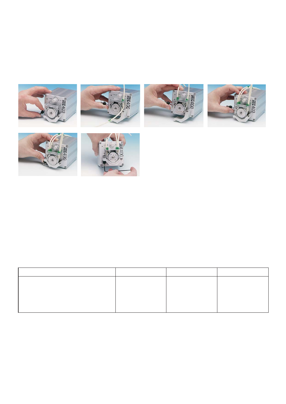
Tube loading
•
Release the track by disengaging the sprung track pin.
•
Locate the first tube bridge into the appropriate tube bridge holder slot. Feed the tubing in around the
rotor. Locate the centre tube bridge into the bridge holder slot immediately opposite the first tube bridge.
Repeat for the remaining one (400DM2) or two (400DM3) channels. Make sure that there are no twists or
kinks in the tubing after loading as this will adversely affect tube life.
Tube removal
•
Release the track by disengaging the sprung track pin.
•
Remove both tubing bridges from their location slots and remove the tubing from the pumphead.
Pumphead spares
Description
400D1
400DM2
400DM3
Track
940418
940418
940920
Track latch (occlusion) arm
010038
010038
010038
Rotor
010014
010015
010016
Tube clamps
010041
000107
000078
Rotor screw
MRX M4X6 A4
MRX M4X6 A4
MRX M4X6 A4