Watson-Marlow EC 25 User Manual
Page 11
Revision 4.4 / November 2010
11
11 Changing the connection position
12 Changing the direction of rotation
13 Important: Observe before start-up!
If you have performed cleaning or repair work or make the first start-up, check before start-up that all screws are correctly and
completely tightened.
Observe the corresponding regulations in the case of hazardous pumped material (according to ArbStoffV).
The pump can possibly be contaminated by transport, therefore remove the pump cover and clean if necessary before start-up.
Before you start up the pump, convince yourself once again that the scraper and the guide cartridge are in the correct position in
relation to the pressure side (see change of direction of rotation).
The operator must ensure that the pump is installed in an appropriate position with all necessary
safety precautions (sensors, switches, pressure gauges, etc.)!
When the connection position is changed, the motor must be protected
against unintentional switching on!!
C
C
A
A
U
U
T
T
I
I
O
O
N
N
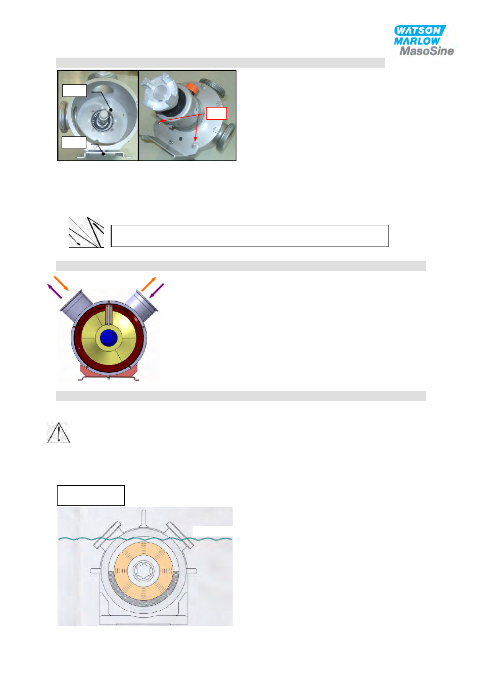
Liquid level
The pump must always be filled with the
corresponding medium before commissioning
and during operation, with the liquid level
above the rotor (see diagram).
Never let the pump run dry!!!
Changing the direction of rotation for a EC 25, EC 40 and EC 60.
Due to construction, the pump is able to turn clockwise as well as
counter clockwise. For doing this any conversion or modification is not
necessary.
All you have to do is changing the direction of the gear motor.
Pos. 10
Pos. 30
Pos. 9
The standard nozzle configuration is set at the 10-2 position from the
factory. To change the nozzle position, all internal parts must first be
removed as in illustration 001. Remove the screw, Pos. 30, as well
as the screws Pos.9 (2 pcs.). The housing and shaft can now be
removed from the baseplate. Note: once removed from the base, the
housing will be free and should be secured to prevent possible
damage or personal injury. CAUTION: EC 40 AND EC 60
HOUSINGS WILL BE HEAVY. Rotate the pump housing into the
desired position and replace the screws to reinstall the baseplate.
The bearing assembly musty now be rotated so that the vent and oil
sight glass are in the proper position. Remove the screws, Pos.10 (4
pcs.) and remove the shaft and bearing housing assembly from the
pump housing. Rotate the bearing housing assembly until the vent is
in the vertical position and reinstall on the pump housing. Tighten the screws Pos.9 according the specified torque. Mind that the shim
kit, Pos. 24 is on the housing.
Torque for Pos. 9: EC 25 25 Nm EC 40 50 Nm EC 60 90 Nm
Observe that the pump is filled with product before starting to facilitate suction and to avoid dry run. (see chapter 12)!