Operators manual, Gd30p – Watson-Marlow GD30P User Manual
Page 6
OPERATORS MANUAL
Machine Type:
GD30P
GD30P OM 1.01 EN
Ver 1.01
Date 2006-10-24
Page 6 of 14
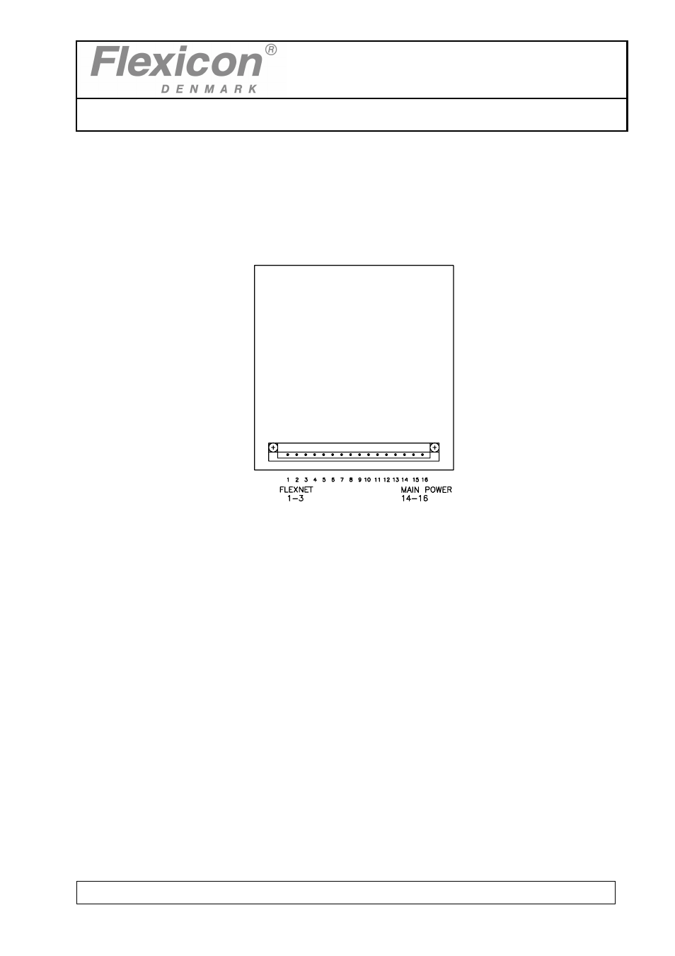
3.3 Installation
GD30P must be placed either in frame delivered or otherwise in a suspension frame. All
electrical connections are on the rear side.
Fig. 1
The power supply is mounted with 0-I pin 4, earth in pin 15 and phase in pin 16.
The communication cable from MC12/MC12P is mounted in pin 1-3.
Should the system be operating more than one GD30P, the communication lines are
connected in parallel in pin 1-3 in all units.
Address "1" is the factory setting of GD30P. In case you want to change this setting,
please consult section 1.4 in this manual.
GD30P is now ready to be switched on and to be programmed from the MC12/MC12P.
See also other documents in the category Watson-Marlow Pumps:
- 323Dz (53 pages)
- 620SN (100 pages)
- Bredel 25 (76 pages)
- APEX35 (72 pages)
- Bredel 80 (76 pages)
- Bredel 15 (68 pages)
- 520Bp (107 pages)
- 323D (48 pages)
- EBU250 (8 pages)
- FF20 (24 pages)
- MR-Series (52 pages)
- EC 60 (28 pages)
- PetroProof Series (49 pages)
- Qdos30 Universal (40 pages)
- Qdos60 Universal 110V Logic (78 pages)
- 120S/DM3 (36 pages)
- 120F/DV (26 pages)
- SP50 (86 pages)
- 101U (14 pages)
- 505BA (21 pages)
- 700 series (11 pages)
- Qdos60 Profibus (66 pages)
- 521CC (47 pages)
- 401U (12 pages)
- 620RE4A (11 pages)
- 405U (13 pages)
- 624S (46 pages)
- Bredel 2100 (92 pages)
- Bredel 2100 (96 pages)
- 701 (25 pages)
- 840 (13 pages)
- 505LGA (11 pages)
- 620RE4 (19 pages)
- 205U (13 pages)
- SPS (142 pages)
- 505U (19 pages)
- 704S (17 pages)
- 621 Trio (11 pages)
- 313T (16 pages)
- 624Di (37 pages)
- 505Di (39 pages)
- 501CC (17 pages)
- 504Du (31 pages)
- 504Du (30 pages)