Ordering information, Connections – Verilink 400 (34-00222) Product Manual User Manual
Page 7
10
7
You may obtain an RMA number from customer service at 800-926-0085 extension
2282. When calling TxPORT for an RMA, please have the following information avail-
able.
•
Model number and serial number for each unit.
•
Reason for return and symptoms of problem.
•
Warranty status (if known).
•
Purchase order number to cover charges for out-of-warranty items.
•
Name and phone number of person we can contact if we have questions about the
unit(s).
•
Mode of shipment required (second-day air is the normal mode of shipment for all
returned material unless otherwise specified).
Units being returned to TxPORT should be sent to the following address.
TxPORT
127 Jetplex Circle
Madison, Alabama 35758
Ordering Information
You may require additional items to install and operate each unit. Use the following
numbers to order the basic unit or optional equipment.
Part Number
Description
F- 400- 001 -- 111
Productivity Series Multirate 400 DSU/CSU unit
9- 2000 - 001 - 1
Single unit horizontal rack mount hardware for 19-inch equipment rack
9- 2000 - 001 - 2
Dual unit horizontal rack mount hardware for 19-inch equipment rack
9- 2000 - 002 - 1
Single unit horizontal rack mount hardware for 23-inch equipment rack
9- 2000 - 002 - 2
Dual unit horizontal rack mount hardware for 23-inch equipment rack
9- 2000 - 001 - 8
19-inch multi-unit rack mounting for eight units.
9- 2000 - 002 - 8
23-inch multi-unit rack mounting for ten units.
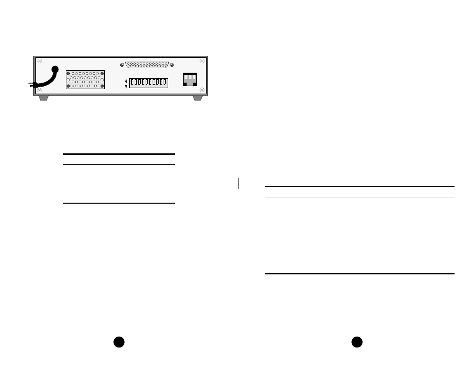
Connections
The 400 DDS rear panel has three interface connectors: an RJ-48C DDS network
connector, a V.35 high speed port connector, and an RS-232 connector. Each unit
comes equipped with a power cord for 115 VAC operation (±10%).
DDS Network Connection
The network DDS facility interface is a standard RJ-48C (8-pin) modular jack with
the following pinout:
V.35 and RS-232 Port Connection
The V.35 or the RS-232 port is automatically selected when you physically connect
the cable to the port. Connection to only one of these two connectors is allowed at
any one time because the internal circuitry selects the proper interface depending on
which connector has TXD applied. These ports meet all the general physical and
electrical requirements. The V.35 connector is a standard 34-pin female. The RS-
232 connector is a standard DB-25 female.
The V.35 and RS-232 pin assignments are shown in the previous table. Only cir-
cuits serviced by the unit are listed. When two pins are listed, the first is the A differ-
ential pin and the second is the B differential pin. All balanced bipolar inputs and
outputs meet the physical and electrical specifications at ITU V.35. All unbalanced
bipolar inputs and outputs meet the physical and electrical specifications of ITU
V.28.
Pin
Assignment
1
Network Transmit Out
2
Network Transmit Out
3
Not Used
7
Network Data In
8
Network Data In
8
1
DDS
8
6
5
4
3
2
1
7
S1
A
B
V.35
9
115 VAC
13
1
14
25
RS-232
NET
10
TxPORT 400 DDS Rear Panel