Warranty – Verilink 400 (34-00222) Product Manual User Manual
Page 6
6
11
Notice to Users of DDS service: The following instructions are provided to ensure
compliance with FCC Rules, Part 68:
1)
All direct connections to DDS lines must be made using standard plugs and jacks.
2)
Before connecting your unit, you must inform the local telephone company of the
following information:
3)
If the unit appears to be malfunctioning, it should be disconnected from the tele-
phone lines until you learn whether the source of trouble is your equipment or the tele-
phone line. If your equipment needs repair, it should not be reconnected until it is
repaired.
4)
The unit has been designed to prevent harm to the DDS network. If the telephone
company finds that the equipment is exceeding tolerable parameters, they can tempo-
rarily disconnect service. In this case, the telephone company will give you advance
notice, if possible.
5)
Under FCC rules, no customer is authorized to repair this equipment. This restric-
tion applies regardless of whether the equipment is in or out of warranty.
6)
If the telephone company alters their equipment in a manner that will affect the
use of this device, they must give you advance warning so that you can have the oppor-
tunity for uninterrupted service. You will be advised of your right to file a complaint
with the FCC.
7)
The attached affidavit must be completed by the installer.
8)
In the event of equipment malfunction, all repairs should be performed by our
company or an authorized agent. It is the responsibility of users requiring service to
report the need for service to our company or to one of our authorized agents.
Warranty
If for any reason you must return your TxPORT product, it must be returned to the fac-
tory, shipping prepaid and packaged to the best commercial standard for electronic
equipment. TxPORT will pay shipping charges for delivery on return. You are respon-
sible for mode and cost of shipment to TxPORT.
You must have a Return Material Authorization (RMA) number marked on the ship-
ping package. Products sent to TxPORT without RMA numbers will be returned to the
sender unopened, at the sender’s expense. A product sent directly to TxPORT for repair
must first be assigned a Return Materials Authorization (RMA) number.
Port ID
REN / SOC
kbps
FIC
USOC
12 - 00492
6.0 N
2.4
4.8
9.6
38.4
56
64
04DU5-24
04DU5-48
04DU5-96
04DU5-38
04DU5-56
04DU5-64
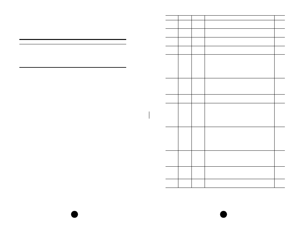
RJ-48C jack
Circuit
V.35
RS-232
Signal Function
(Note: all other pins are open)
DCE
101
A
1
Frame Ground - This circuit is used to terminate
shields.
Gnd
102
B
7
Signal Ground - This circuit is used as the return
reference for unbalanced signals.
Gnd
103
P/S
2
Transmit Data - This input is used for synchronous TD
from the DTE. It is transmitted on the DDS side.
In
104
R /T
3
Receive Data - This output is the data decoded from
the incoming DDS receive data.
Out
105
C
4
Request To Send - This input is a control line from the
DTE indicating data is to be transmitted. When RTS is
On (space), the data transmitter, the zero suppression
circuitry, and the CTS are enabled. When RTS is Off,
the transmitter sends idle code and the CTS is forced
Off.
In
106
D
5
Clear To Send - This output is a DCE response,
indicating that either RTS is On or S1- 8, position B, is
forcing RTS On. When S1 -7 is in position B, RTS and
RLSD must be On for CTS to be On.
Out
107
E
6
Data Set Ready - This output is On when the unit is
not in a test mode (other than a V.54 test).
Out
109
F
8
Data Carrier Detect - This output is On when the
correct data or zero suppression code is being received
and DSR is On. It is Off when either DSR is Off, the
DDS receiver has lost sufficient signal to operate for at
least one second, or the receiver has received OOS,
OOF, idle, or loop codes for about 20 U.I.
Out
113
U /W
24
External Transmit Clock - This is the synchronous
transmit clock input from the DTE. When both S1 - 3
and S1 - 4 are in the B position, this clock controls the
frequency of the DDS transmit clock and clocks
circuit 103 (TD). When either S1 -3 or S1- 4 is in the
A position, this input has no effect on DDS operation.
In
114
Y/AA
15
Transmit Clock - This output is supplied by the DCE
as an external DTE timing source. It is generated from
the internal data clock or the far end transmit data. Not
available when S1 -3 and S1 - 4 are in the B position.
Out
115
V/X
17
Receive Clock - This clock output is the timing for the
RD and is always used to time the receive data. This
clock is always derived from the DDS receive data.
Out
142
K
25
Test Mode - This output is On when the unit is in the
Test/Loop mode.
Out