Tri Tool 214B Miter Mandrel Head Kit User Manual
Page 13
13
Model 214B MM (Miter Mandrel)
92-1505 : Orig. 100923
Parallel Offset Adjustment
As before, use the Indicator Kit to determine how much the Mandrel Shaft
must move, and in what direction.
To move the Mandrel Shaft in a given direction, first loosen the Jackscrew on
the side you wish to move toward.
Now tighten the Jackscrew (and Jam Nut as required) on the opposite side
of the Head Assembly., which you may wish to move away from in order to
push the Mandrel Shaft in a given direction.
Repeat the indicating procedure and the parallel offset adjustment procedure
as many times as necessary to achieve the accuracy desired.
Remove the indicator items and indicator sleeve from the Mandrel Shaft.
Before installing and operating the Model 214B refer to it's 'Operator’s Manual' for
complete machine safety, cautions, warnings and operating instructions.
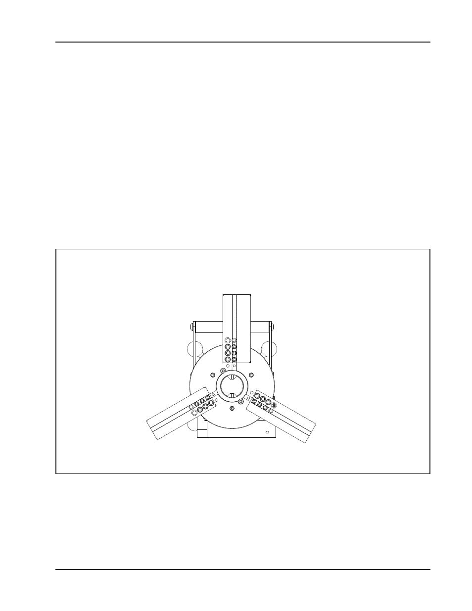
The Tool Block on the Model 214B must be mounted, using the four (4) outer most
bolt holes, so they will clear the Miter Head.
Tool Block Position when using the Miter Mandrel
- 204B Cutting Head (9 pages)
- 204B Cutting Head (10 pages)
- 204B Cutting Head (9 pages)
- 212B Single Point Spring Hanger Assembly (8 pages)
- 204B Cutting Head (13 pages)
- 204B Cutting Head (36 pages)
- 204B Cutting Head (17 pages)
- 201BA Beveler (36 pages)
- 204B Elbow Mandrel (16 pages)
- 204B Beveler (45 pages)
- 204B Flange Facer (21 pages)
- 206B Elbow Mandrel (17 pages)
- 206B Flange Facer (22 pages)
- 206B Beveler (45 pages)
- 212B ID Tracking Module (17 pages)
- 206B Miter Mandrel (16 pages)
- 206B Sleeve Mandrel (13 pages)
- 208B Elbow Mandrel (20 pages)
- 208B ID Tracking Module (18 pages)
- 208B Miter Mandrel (20 pages)
- 208B Flange Facer (28 pages)
- 208B Sleeve Mandrel (15 pages)
- 212B Elbow Mandrel (16 pages)
- 214B Beveler Single Point Flange Facer (41 pages)
- 212B Flange Facer (22 pages)
- 212B Miter Mandrel (20 pages)
- 212B Single Point Hydraulic Motor Assembly (9 pages)
- 212B Single Point Flange Facer Miter Mandrel (28 pages)
- 212B Sleeve Mandrel (12 pages)
- 214B Elbow Mandrel (20 pages)
- 214B Flange Facer (23 pages)
- 214B ID Track Module (19 pages)
- 214B Sleeve Mandrel (13 pages)
- 236B ID Tracking Module (23 pages)
- 224B Miter Mandrel (27 pages)
- 224B Single Point (30 pages)
- 230B Beveler Flange Facer (16 pages)
- 230B ID Tracking Module (15 pages)
- 230B Lifting Frame (19 pages)
- 236B Miter Mandrel (25 pages)
- 301SP Tube Squaring (35 pages)
- 236B Single Point (32 pages)
- 302 Tube Squaring Micro Feed Assembly (11 pages)
- 302 Tube Squaring (31 pages)