Installation procedures – Thermon HSX User Manual
Page 7
7
INSTALLATION PROCEDURES
Final Inspection and Documentation . . .
1. It is recommended that the circuit be temporarily energized
so that the volts, amps, pipe temperature and ambient
temperature may be recorded. This information may be of
value for future reference and should be maintained for the
historical operating data log (Record 4 on Cable Testing
Report).
2. Once power is connected but before putting the system
into operation, verify all heating cable testing and documen-
tation have been completed for each heat tracing circuit.
This will ensure that the system has been installed per the
manufacturers recommendations.
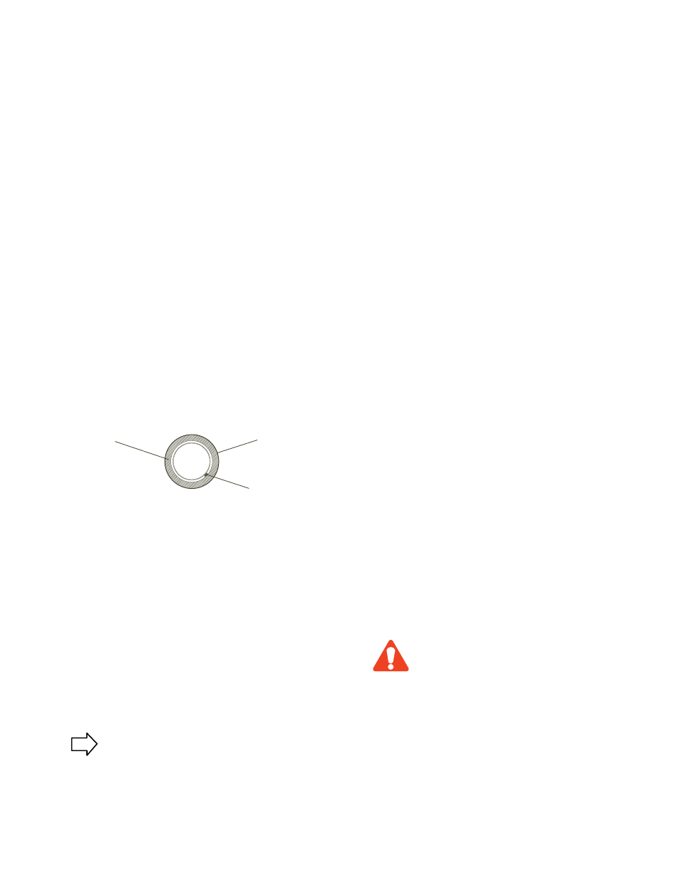
Thermal Insulation with Weather Barrier
Heating Cable
(Typical)
Weather Barrier
Thermal Insulation
Record the location of all terminations on plumbing
drawings after each termination has been completed.
This will ensure that no terminations are overlooked
and will document the extent of the heat tracing on
the drawing.
Thermal Insulation . . .
1. The need for properly installed and well-maintained thermal
insulation cannot be overemphasized. Without insulation,
heat losses are generally too high to be offset by a conven-
tional heat tracing system.
2. Regardless of the type or thickness of insulation used, a
protective barrier should be installed. This protects the in-
sulation from moisture intrusion, physical damage and helps
ensure the proper performance of the heat tracing system.
Seal around all penetrations through the thermal insulation.
3. After the installation of the thermal insulation and weather
barrier but BEFORE ENERGIZING THE HEATING CIRCUIT,
the megohmmeter test should be repeated. This should call
attention to any damage to the heating cable that may have
occurred during the insulation installation. (Record 3 on
Cable Testing Report)
4. Apply caution labels to insulation weather barrier at required
intervals along pipe
Start-Up Procedure . . .
When a WarmTrace system has been installed per this guide,
start-up is easy. Simply follow the steps listed below. Please
note that the operating current for the cable will be higher
during start-up than during normal operating conditions. This
is because the water in the heat trace piping is usually at the
building ambient temperature. This condition has been ac-
counted for in the breaker sizing and current length table pro-
vided so long as the ambient temperature is at or above 15˚C
(60˚F).
1. On closed loop systems a valve or faucet should be partially
opened to prevent excessive pressure accumulation as tem-
peratures rise.
2. Energize the heating cable and allow the system to reach its
equilibrium temperature. The building water heater should be
operating and the building's environment should be at ambi-
ent temperature 22˚C-27˚C (72˚F-80˚F).
3. The water heater/mixing valve which controls the water
supply temperature should be set at the same temperature
as the heating cable's nominal value i.e. 45˚C (105˚F), 49˚C
(120˚F) or 60˚C (140˚F) Variations greater than ±5°C (10˚F)
could cause noticeable swings during operation.
4. Using a calibrated thermometer, check the water tempera-
ture at the water heater to be certain that it is within the
desired range.
5. Again, using a calibrated thermometer, check the water
temperature at various tap locations that are heat traced. Al-
low sufficient time for water to pass any unheated portion of
water line.
6. Test for ground-fault protection by manually tripping the
push-to-test button on the device (remember to reset after
the test).
If start-up is not successful, refer to the Trouble Shooting sec-
tion of this guide for assistance.
Disconnect power to heating cable (turn off
circuit breakers) during water heater start-
up and hot water system purging if water
temperature will exceed 65˚C (150˚F).
CAUTION
TIP