Warmtrace – Thermon HSX User Manual
Page 4
4
WarmTrace
TM
HSX
Prior to Installing Cable. . .
1. Verify Electrical Resistance with a megger.
• Refer to Cable Testing Section in this Installation Guide for
details.
2. Inspect the piping to be heat traced.
• Verify that the pipe has been pressure tested, and that all
pipe supports are in place.
• Compare layout of the installed piping vs plumbing
drawings.
3. Surface areas where heat tracing is to be installed must be
reasonably clean. Remove dirt, rust and scale with a wire
brush and oil or grease films with a suitable solvent.
4. Plan the installation.
• Some of the hot water supply may not require heating
cable. Note the extent of heat tracing required by
reviewing:
1. Project specification
2. Plumbing drawings
3. Drawings supplied by Thermon (If a drawing package
was part of heat trace system).
• Allow sufficient cable to cover the longest runs first. This
will insure that no additional cable or splice kits will be
required.
• The extent of heat tracing, location of power connection
points, splice and end terminations can be temporarily
identified with marking ribbon or spray paint.
5. Identify the heat tracing materials.
• The cable should have been identified upon receipt. Be
sure to make note that more than one water maintain
temperature, and therefore more than one HSX cable, may
be required for the project.
• Familiarize yourself with the connection kits and accessory
components included with the bill of materials.
Power Connection Points: The power (electrical) connec-
tion points must remain accessible, even after the building is
completed. If the facility will be finished out with a suspended
ceiling, power connection points can be located anywhere that
is convenient and accessible to electrical power. If the finished
ceiling is permanent, each power connection point should be
located within reach from the access door.
Tee Splice Connections and End Terminations: Thermon rec-
ommends that wherever possible, all connections and termi-
nations be located in an area that allows future access should
changes or additions to the plumbing system be needed.
Initial Installation. . .
Begin temporary installation at the proposed end-of- circuit
location and lay out heating circuit on pipe, allowing extra cable
for the power connection and for any splice locations.
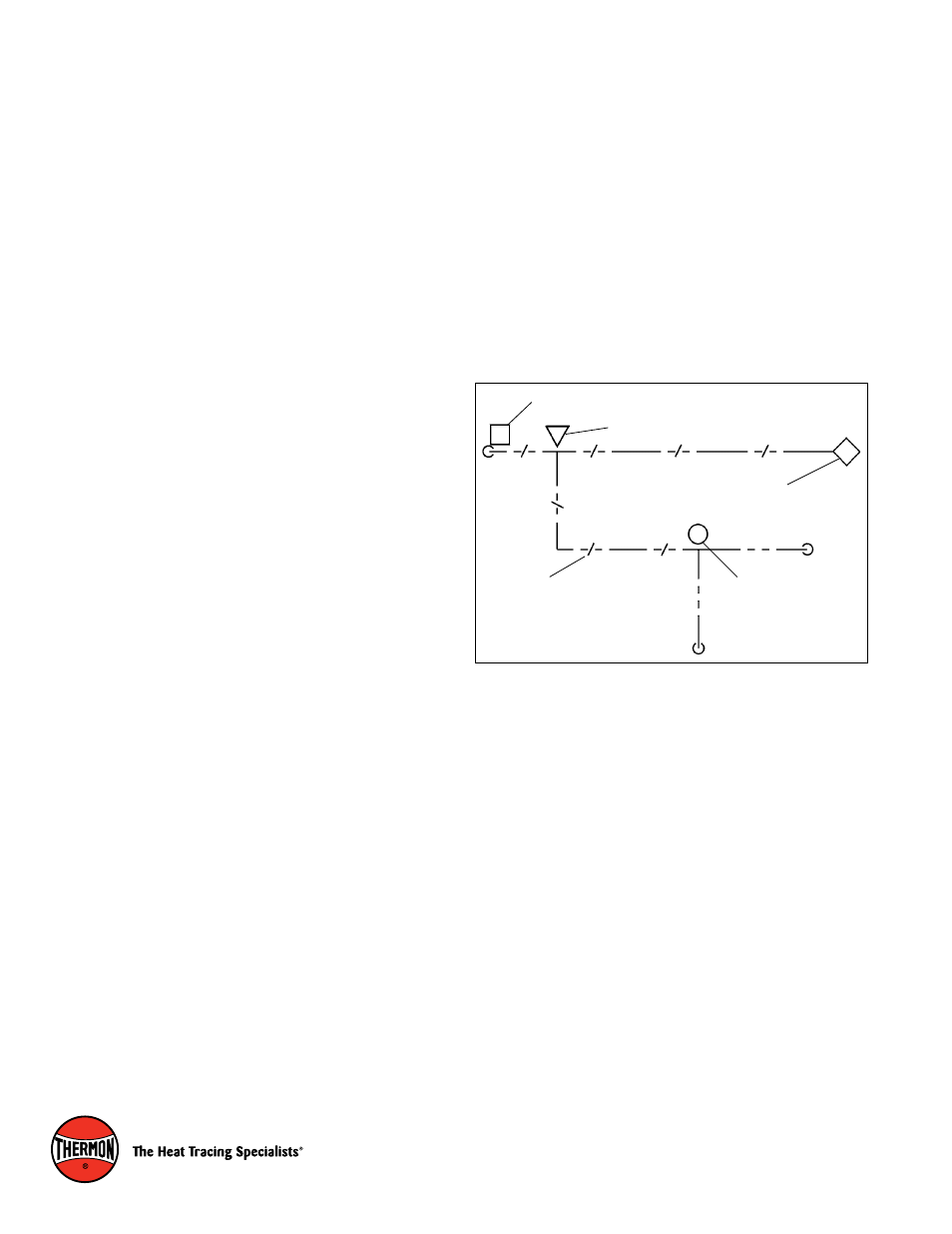
Locating Power, Tee and End Termination: Refer to the
plumbing, electrical or Thermon supplied drawings to deter-
mine the locations for connections and terminations. The sym-
bols below are routinely used to show the various components
of a heat trace hot water supply system. Note that the electrical
drawings will typically only show the power connection point.
Circuit Continued on Another Sheet
Electrically Heat-Traced Hot Water Line
Heating Cable T-Splice Kit
End-of-Circuit Termination
Power Connection Point