Fak-4 and fak-4l: in-line splice, Installation procedures – Thermon FAK-4 User Manual
Page 3
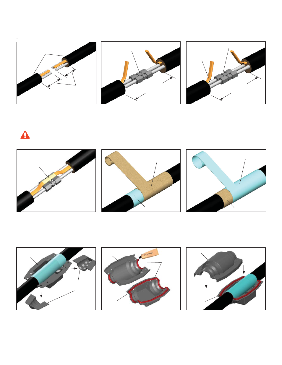
4.
Wrap tube and heat trace with 1 pass of refl ective
tape (25% overlap), then wrap with 3 passes of
glass fi ber tape (50% overlap), or until fi ber tape
is equal to original bundle insulation thickness.
2.
Cut 38mm (1.5”) off the end of the tubing and make
tube fi tting connections with appropriate fi ttings,
provided by others. If no electrical heat trace is
present, go to Step 5.
5.
Complete with additional passes of heat refl ective
tape.
1.
Remove outer jacket and insulation from tubing
bundle approximately 127 mm (5”) from end of the
tubing bundle. Where required ensure suffi cient heat
trace is available for electrical splice. See instructions
included with heat trace kit.
127 mm
(5”)
Tubing Bundle
(SE/ME Shown)
Cut and Discard
End Pieces
Splice Cover
178 mm
(7”)
Heat Tracing Splice
(if required)
3.
If bundle includes electric heat trace, make-up splice
per instruction included with heat trace kit. This
should be accomplished after fi ttings are leak tested.
6.
Cut top and bottom splice cover ends to match
outside diameter of tubing bundle.
7.
Form a gasket by applying RTV sealant to bottom
half of splice cover and along radius of upper half.
8.
Fit tubing bundle to bottom half of cover and install
top half. Screw down fi rmly. Inspect ends of tubing
splice cover for snug fi t. Apply additional RTV sealant
where needed.
RTV
Sealant
Splice Cover
Top
Tubing Fitting
Splice Cover
Bottom
Splice Cover
Top
Splice Cover
Bottom
2
Do not cut or damage the heat trace.
(Found on TubeTrace SE/ME bundles)
CAUTION
FAK-4 and FAK-4L: In-Line Splice
INSTALLATION PROCEDURES
2a.
Zone Type Heat Tracing Only:
If bus connection indentation is less than 38mm
(1.5”) from end of the heat tracing, proceed stripping
the bundle insulation to the next indentation.
178 mm
(7”)
Tubing Fitting
Bus Connection
Indentations
(Zone Heater Only)
Heat Refl ective Tape
Glass Fiber Tape
Heat Refl ective Tape
Glass Fiber Tape