Installation procedures, Tubing installation, Inspection of system – Thermon ThermoTube Type SL User Manual
Page 3
2
Tubing Installation . . .
1. For ease of installation and maintenance, route multiple
runs of ThermoTube symmetrically utilizing the most ac-
cessible path possible. Routing should take advantage of
existing cable trays, angles, channels, struts and I-beams
for support. Maintain a 12 mm minimum clearance be-
tween lines (see Illustration B).
2. ThermoTube must maintain a 20 mm per metre minimum
slope toward the tracer, supply station or condensate re-
turn header to avoid trapping water during shutdown peri-
ods.
3. Secure ThermoTube to support structure every 1.5 to 1.8 m
on horizontal straight runs and every 3 to 4.5 m on verti-
cal runs. Provide additional support within 450 mm of any
connection point or transition fitting and within 150 to
250 mm of any bends.
4. Cable trays and channel struts provide optimal support for
multiple passes of ThermoTube. Secure ThermoTube to
cable tray using UV resistant plastic cable ties, or prefera-
bly stainless steel banding, while utilizing cable clamps or
standard conduit straps for channel strut attachment (see
Table 1 for conduit strap sizing). Use caution when secur-
ing ThermoTube to structure. Do not crush the thermal in-
sulation and outer jacket.
5. As an option, angle iron may be used to support Thermo-
Tube on long vertical and horizontal runs. Angle iron
should be sized approximately 12 mm larger than the tub-
ing O.D. Place the angle over the ThermoTube to prevent
moisture buildup. Secure ThermoTube to the angle using
UV resistant cable ties or stainless steel banding, as out-
lined in step 3 of the tubing installation.
6. Contact factory to obtain recommended maximum Ther-
moTube lengths relative to steam pressure.
7. A time proven empirical method used by Thermon is to
limit the accumulated vertical rise "AVTR" in bar g, to
0.666 of the inlet steam pressure. For example, using a
steam pressure of 10.35 bar g X 0.666, the AVTR would
be approximately 6.89 m.
Inspection of System . . .
1. Verify that ThermoTube is properly secured to the support
structure without causing deformation to the insulation
and outer jacket.
2. Thoroughly inspect ThermoTube after installation is com-
plete to ensure all bends are free of kinks and wrinkles
and that flattening has not occurred. Refer to the bending
guidelines on page 1 of these installation procedures.
3. Properly terminate and seal all open ends of ThermoTube
using the FAK-7 end seal kit and FAK-8 patch kit. Refer to
the illustrations on page 3.
4. Clean the tubing before connection. After all connections
to the steam tracers, supply header and collection mani-
folds have been completed, test the circuit for leaks by
subjecting it to steam pressure equal to or greater than
that which is to be used in the system, or preferably with
suitable hydrostatic tests. Repair any leaks and retest the
system.
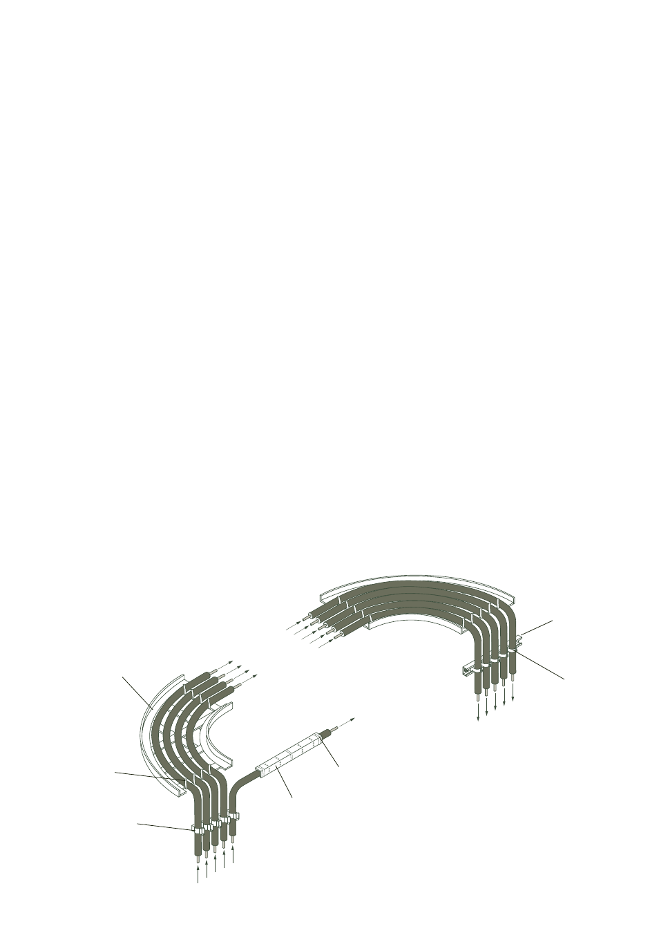
Illustration B: Typical ThermoTube Installation
From Heat Tracers
To Heat Tracers
Standard Cable Tray
(Typical)
Plastic Cable Tie
(Typical)
From Steam Supply Manifold
Perforated Angle
Iron Support
To Condensate
Collection Manifold
Conduit Straps
(Typical)
Channel Strut
(Typical)
To Heat Tracers
Plastic Cable Tie
(Typical)
INSTALLATION PROCEDURES
Cable Clamps
(Typical)