Thermotube, Type sl, Receiving, storing and handling – Thermon ThermoTube Type SL User Manual
Page 2: Tubing layout, Bending procedure
1
The following installation procedures are suggested guide-
lines for the installation and support of ThermoTube preinsu-
lated steam supply and condensate return tubing. They are
not intended to preclude the use of other methods and good
engineering or field construction practices.
Receiving, Storing and Handling . . .
1. Inspect materials for damage incurred during shipping. Re-
port damages to the carrier for settlement.
2. Identify the ThermoTube type to ensure the proper materi-
al and quantity has been received. Boxes and reels are
marked on the outside with the ThermoTube part number,
length, product description, weight and customer pur-
chase order number. Compare information on box or reel
with packing slip and purchase order to verify receipt of
correct shipment.
• Lengths shorter than 25 m are shipped in
heavyweight cardboard boxes.
• Lengths greater than 25 m are shipped on
nonreturnable wooden reels.
3. The ends of ThermoTube are factory-sealed to prevent
dirt, moisture and insect intrusion. As a preventive mea-
sure, keep ends sealed until final connections are made.
Cut ends may be temporarily sealed with plastic wrap and
tape.
4. Cardboard boxes and wooden reels of product should be
stored indoors away from standing water. However, wood-
en reels may be stored outdoors using a protective cover-
ing.
5. ThermoTube is shipped with the end of the tubing strap-
ped to the side of the wooden reel. Use caution when re-
leasing the end of the tubing from the reel as it is under
tension and may recoil when released.
Tubing Layout . . .
1. Determine lengths and number of fittings prior to uncoil-
ing ThermoTube since uncoiling and recoiling will “work
harden” the tubing.
2. Position reel such that ThermoTube may be pulled from
the reel toward the least accessible end point allowing in-
stallation to begin at the end point working back toward
the reel.
3. To uncoil and straighten ThermoTube, anchor the loose
end of the tubing on a flat surface and roll the hand coil or
shipping reel. If additional straightening is needed, apply
tension to the tube.
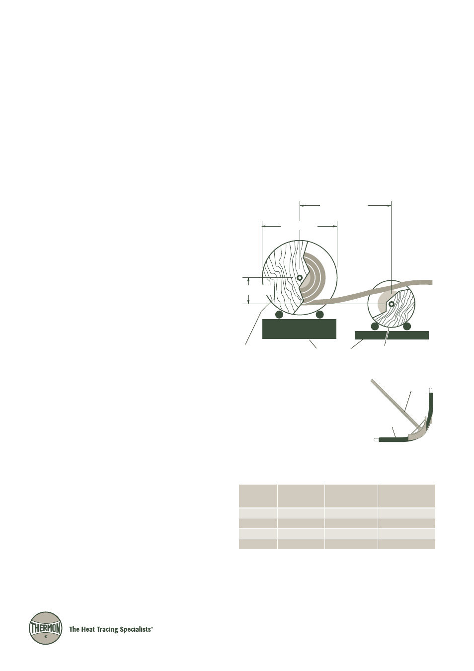
4. Wooden spools of ThermoTube containing long lengths of
tubing can be placed on a pay-off tray as shown in Illustra-
tion A below. To “pay-off” ThermoTube, place the reel con-
taining the tubing on one tray allowing the tubing to freely
spool from the bottom of the reel.
5. Straighten ThermoTube by utilizing a counterspool located
in front of the reel containing the tubing (see Illustration
A). The counterspool should be located at a distance of
2½ times the diameter of the ThermoTube reel. Include a
vertical offset of 200 to 250 mm between the reel centers.
2.5 x Diameter A
200-250 mm
Diameter A
ThermoTube Reel
Counterspool
Pay-off Trays
Illustration A: Tubing Payout
Bending Procedure . . .
1. ThermoTube must be bent so there
is no strain on the fitting after the
tubing is installed. The cross-section-
al area of ThermoTube should not be
flattened, kinked or wrinkled. Refer
to Table 1 for the minimum accept-
able bending radius for each Ther-
moTube type. Use a properly sized conduit bender or
mechanical tubing bender to assure constant radius bends
where possible.
Table 1: ThermoTube Bending
1
and Fastener Allowance
Notes . . .
1. Make bends with a mechanical tubing bender. Other types of benders can also be
used if care is taken to prevent deforming or flattening of the tube.
2. The bending radius for each ThermoTube type is based on the outside diameter of
the protective jacket.
ThermoTube
®
Type SL
.
a
i
D
e
b
u
T
.
D
.
O
m
m
e
b
u
T
o
m
r
e
h
T
.
D
.
O
m
m
s
u
i
d
a
R
d
n
e
B
.
n
i
M
2
m
m
d
e
d
n
e
m
m
o
c
e
R
e
z
i
S
p
a
r
t
S
t
i
u
d
n
o
C
)
6
(
4
/
1
)
9
2
(
5
1
.
1
8
7
1
d
i
g
i
R
m
m
0
2
)
0
1
(
8
/
3
)
2
3
(
5
2
.
1
8
7
1
T
M
E
m
m
0
5
)
2
1
(
2
/
1
)
4
3
(
5
3
.
1
3
0
2
d
i
g
i
R
m
m
0
5
)
9
1
(
4
/
3
)
6
4
(
8
.
1
4
5
2
T
M
E
m
m
0
4
Mechanical
Tube Bender
ThermoTube