Terminator, Ecm-ambient-wp, Installation procedures – Thermon ECM-Ambient-WP User Manual
Page 3: 3the heat tracing specialists
3
The Heat Tracing Specialists
®
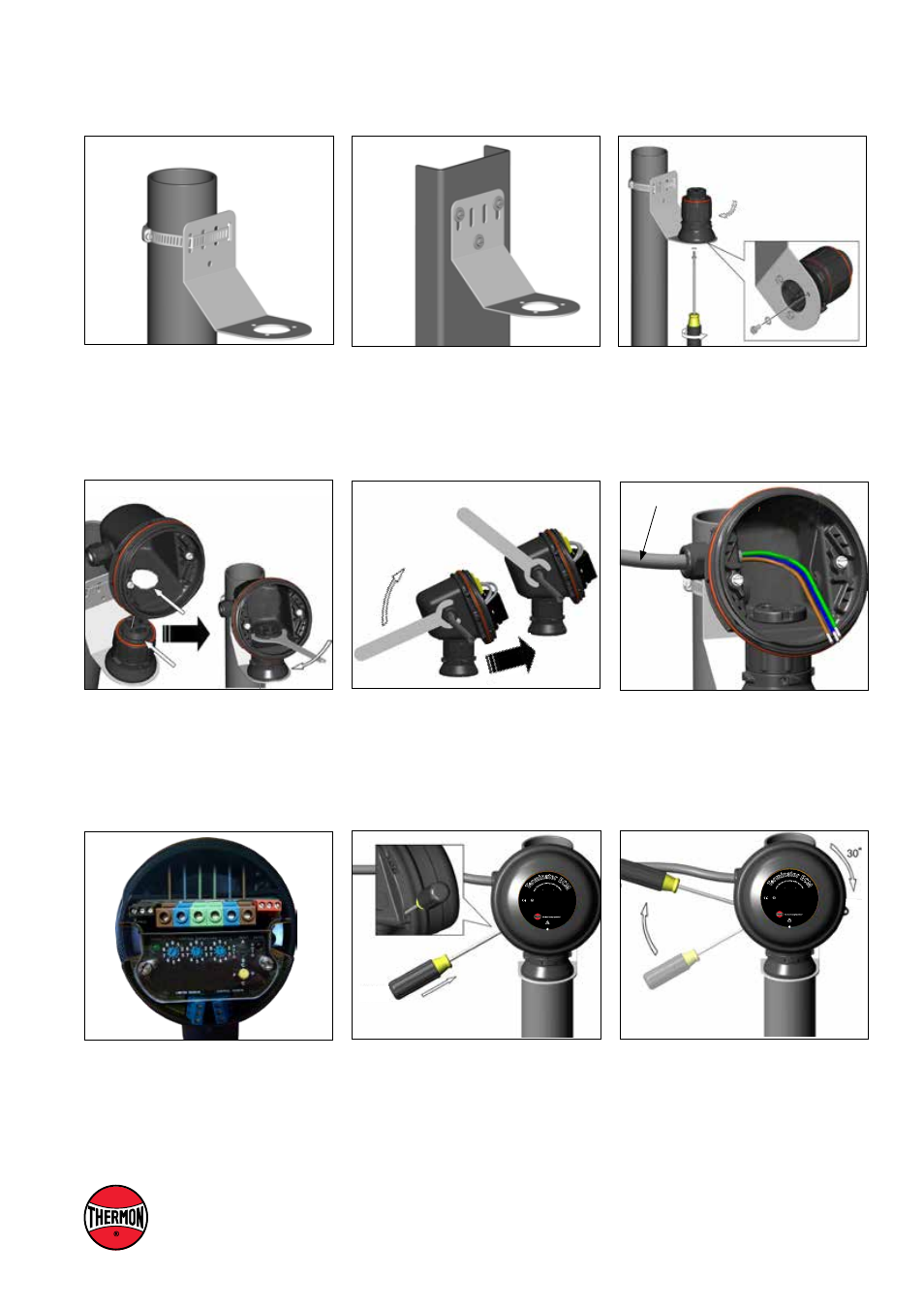
3.
Mount junction box base on expediter.
Make sure to align slots to properly
orient junction box base. Tighten nut with
Terminator-LN-Tool.
2.
Mount expediter to bracket using
M5 x 8mm screws and M5 lock washers.
Tighten cap securely.
1b.
Mounting Method 2: Secure wall mount
bracket to mounting surface using
customer supplied screws, flat washers,
and nuts.
1a.
Mounting Method 1: Secure wall mount
bracket to mounting surface using pipe
band provided with kits.
Power Cable
5.
Install power cable and RTD. Stainless
steel RTD tip must extend ≥ 20 mm out
of gland.
4.
Remove M25 dust cap. In
stall M25 power
gland (order separately) and M25 blind
plug.
6.
Install electronic control module and
complete system wiring. Terminal set
screws shall be tightened to a torque
value of 1,4 Nm (12,4 lb-in). See wiring
details. Set module electronic control at
desired setpoint.
1725 II 2 GD Ex eb mb [ib]ib IIC T4, Ex tb IIIC T135°C
SIRA 12ATEX5239X
IP66
-60°C ≤ Ta ≤ + 55°C
IECEx SIR 12.0103X Ex eb mb [ib]ib IIC T4, Ex tb IIIC T135°C
PN 27673
Do
no
t op
en w
hile energ
ized. See insta
llatio
n in
str
uc
tio
ns
.
Te
rmi
nator EC
M
Fo
r u
se
as
an a
djusta
ble electronic co
ntrol
mo
dule
8.
Use screwdriver to ratchet on junction
box lid. Lid will rotate 30 degrees. To
remove lid, repeat steps 7 and 8 but in
the opposite direction.
7.
Install junction box lid and twist hand
tight. Insert screwdriver into ratchet slots
located on side of junction box base.
1725 II 2 GD Ex eb mb [ib]ib IIC T4, Ex tb IIIC T135°C
SIRA 12ATEX5239X
IP66
-60°C ≤ Ta ≤ + 55°C
IECEx SIR 12.0103X Ex eb mb [ib]ib IIC T4, Ex tb IIIC T135°C
PN 27673
Do
no
t op
en w
hile energ
ized. See insta
llatio
n in
str
uc
tio
ns
.
Te
rmi
nator EC
M
Fo
r u
se
as
an a
djusta
ble electronic co
ntrol
mo
dule
Terminator
TM
ECM-Ambient-WP
INSTALLATION PROCEDURES