Terminator, Ecm-ambient-wp, Installation procedures – Thermon ECM-Ambient-WP User Manual
Page 2
2
Certifications/Approvals . . .
Kit Contents . . .
1
2
6
4
3
8
5
7
9
Warnings . . .
• Due to the risk of electrical shock, arcing and fire caused
by product damage or improper usage, installation
or maintenance, a ground-fault protection device is
required.
• Installation must comply with Thermon requirements
(including form PN 50273U for Ex systems) and be
installed in accordance with the regulations as per the
norm EN IEC 60079-14 for hazardous areas (where
applicable), or any other applicable national and local
codes.
• Component approvals and performance ratings are
based on the use of Thermon specified parts only.
• De-energize all power sources before opening enclosure.
• Avoid electrostatic charge. Clean only with a damp cloth.
• Keep kit components dry before and during installation.
• Individuals installing these products are responsible
for complying with all applicable safety and health
guidelines. Proper Personal Protective Equipment (PPE)
should be utilized during installation. Contact Thermon
if you have any additional questions.
The following installation procedures are guidelines for the
installation of the Terminator ECM-Ambient-WP Kit. For
translations other than English and local language translation
provided here, please contact Thermon. The English
language installation procedure shall govern.
Receiving, Storing and Handling . . .
1. Inspect materials for damage incurred during shipping.
2. Report damages to the carrier for settlement.
3. Identify parts against the packing list to ensure the
proper type and quantity has been received.
4. Store in a dry location.
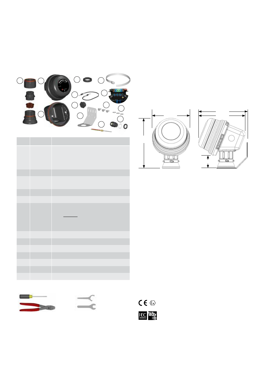
Dimensions . . .
II 2 (2) G Ex eb mb [ib] IIC T4, Ex tb IIIC T135°C SIRA 12ATEX5239X
II 2 (2) D Ex tb IIIC T135°C IP66 Db
International Electrotechnical Commission
IEC Certification Scheme for Explosive Atmospheres
SIR 12.0103X
1725
II 2 GD Ex eb mb [ib]ib I
IC T4, Ex tb I
IIC T135°C
S
IRA 12ATE
X5239X
IP66
-60°C ≤ Ta
≤ + 55°
C
IECEx SIR 12.0103X Ex eb mb [ib]ib I
IC T4, Ex tb I
IIC T135°C
PN 27673
Do n
ot op
en while energized. See ins
talla
tio
n i
ns
tru
ct
io
ns
.
Te
rm
inator ECM
Fo
r u
se
as
an
ad
just
able e
lectronic contro
l mo
dule
10
11
Tools Required . . .
Terminator-LN-Tool
(order separately)
3 mm
8 mm
28 mm
33 mm
Crimp Tool 2,5mm
2
Terminator
TM
ECM-Ambient-WP
INSTALLATION PROCEDURES
190mm
50mm
155mm
200mm
205mm
Manuals . . .
• For operating and monitoring please refer to ECM user
manual and ECM DCS guide.
13
12
Item Quantity
Description
1
1
Expediter Assembly
Support Cap with O-Ring
Threaded Grommet Compressor
Grommet
Support Base with O-Ring
2
1
Junction Box Lid
3
1
Junction Box Base with O-Ring and M25
Dust Cap
4
1
Expediter Nut
5
1
Banding
6
1
Electronic Control Module w/ Terminal Blocks
(Refer to terminal specifications for maximum allowable wire size)
ECM Type*
C - Controler
L - Limiter
CL - Controller/Limiter
* The maximum pipe exposure temperature is limited to 250°C
7
1
Junction Box Lid Cord
8
2
Blind Plug
9
1
Bracket
10
3
Screws
11
3
Washers
12
1
RTD Gland
13
1
RTD