Terminator, Zt-p-wp, Installation procedures – Thermon ZT-P-WP User Manual
Page 4: Fix thermostat bulb and capillary tube to pipe
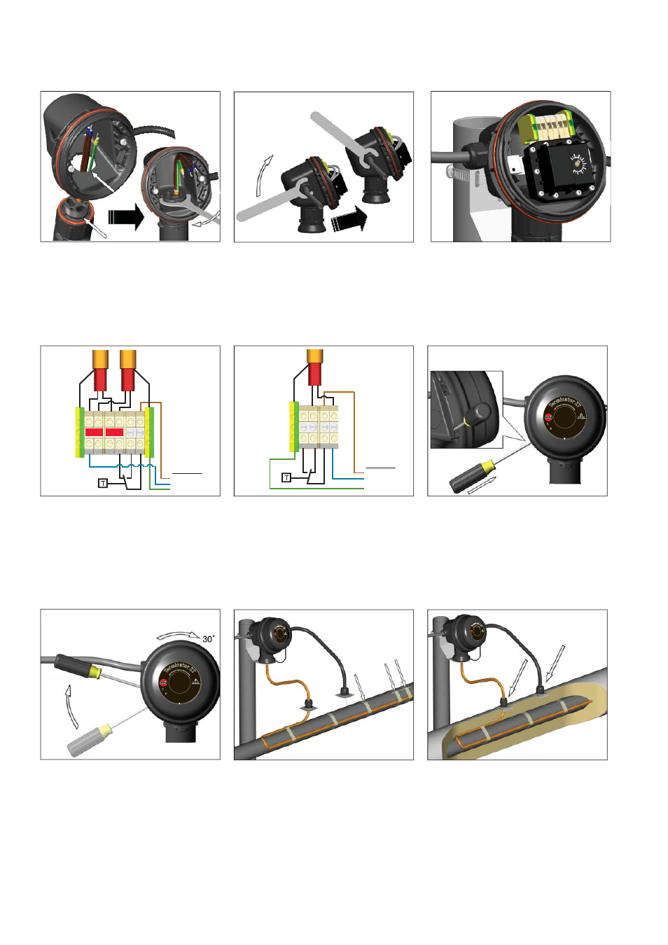
9.
Mount junction box base on expediter.
Make sure to align slots to properly
orient junction box base. Tighten nut
with Terminator-LN-Tool. If mounting
horizontally, threaded gland holes must
face downward.
Te
rm
inator ZT
IP66
-45
°C Ta + 55°C
Fo
r u
se
as
an
adjust
able control th
erm
osta
t
w
ith
T
he
rm
on h
eating cable
sys
tem
s
II 2 G & D EEx ed II C T5
0539
DEMKO 02ATEX132552X
Te
rm
inator ZT
IP66
-45
°C Ta + 55°C
Fo
r u
se
as
an
adjust
able control th
erm
osta
t
w
ith
T
he
rm
on h
eating cable
sys
tem
s
II 2 G & D EEx ed II C T5
0539
DEMKO 02ATEX132552X
Power Supply
L1
N
PE
Heat Trace #1
Heat Trace #2
17
25
I
I 2
GD
Ex d
b eb IIC
T5-T6, Ex tb IIIC
T10
0°C
-T8
5°
C,
F
M
1
0A
TE
X0
0
5
8
X
IEC
Ex F
MG 1
0.0022X
Ex db
eb I
IC T
5-T
6,
Ex
tb
II
IC
T
10
0°
C
-T
8
5
°C
PN 27656
Te
rm
inator Z
T
Fo
r u
se
as
an
adj
ustable
control/lim
iter th
erm
ost
at
IP
6
6 -
60
°C
≤
Ta ≤
+50
°C T5, 100°C; -60°C ≤
Ta
≤
+4
0°
C
T6
, 8
5°
C
1
7
2
5
II
2 G
D E
x db e
b IIC T5-T6, Ex tb IIIC T
100
°C-
T8
5°
C,
F
M
1
0
A
T
E
X
0
0
5
8
X
IEC
Ex F
MG 1
0.0022X
Ex db
eb
IIC
T5
-T6
, E
x
tb
II
IC
T
1
0
0
°C
-T
8
5
°C
PN 27656
T
er
minator
ZT
Fo
r u
se
as
an
adj
ustable
control/lim
iter t
he
rm
os
ta
t
IP
6
6
-6
0
°C
≤
Ta
≤ +
50°C
T5, 100°C; -60°C ≤
Ta
≤
+
40
°C
T
6
,
8
5
°C
1
7
2
5
II 2
G
D E
x db e
b IIC T5-T6, Ex tb IIIC T
100
°C-
T8
5°
C,
F
M
1
0
A
T
E
X
0
0
5
8
X
IEC
Ex F
MG 1
0.0022X
Ex db
eb
IIC
T5
-T6
, E
x
tb
II
IC
T
1
0
0
°C
-T
8
5
°C
PN 27656
Te
rm
inator
ZT
Fo
r u
se
as
an
adj
ustable
control/lim
iter t
her
m
os
ta
t
IP
6
6
-6
0
°C
≤
Ta
≤ +
50°C
T5, 100°C; -60°C ≤
Ta
≤
+
40
°C
T
6
,
8
5
°C
2
2
4 L1
N
N
PE
PE
Terminator
TM
ZT-P-WP
INSTALLATION PROCEDURES
10.
Remove M25 dust cap. Install M25
power gland (order separately) and M25
blind plug. Install power cable
11.
Install thermostat and complete system
wiring. Terminal set screws shall be
tightened to a torque value of 1.4 Nm
(12.4 lb-in). See Step 13 for wiring
details. Set thermostat at desired
setpoint.
12.
Wiring Details: Thermostat Connection
(1 or 2 Heating Cables)
14.
Install junction box lid and twist hand
tight. Insert screwdriver into ratchet
slots located on side of junction box
base.
15.
Use screwdriver to ratchet on junction
box lid. Lid will rotate 30 degrees. To
remove lid, repeat steps 14 and 15 but in
the opposite direction.
16.
Fix thermostat bulb and capillary tube to
pipe.
17.
Install IEK insulation entry kit to seal
heating cable penetration through
insulation cladding.
13.
Thermostat Connection (1 Heating Cable
Shown) 400 Vac Option.
Power Supply
L1
N
Heat Trace
2
L1 N
4
PE
PE