Terminator, Zp-ptd100-wp, Installation procedures – Thermon ZP-PTD100-WP Terminator User Manual
Page 5
5
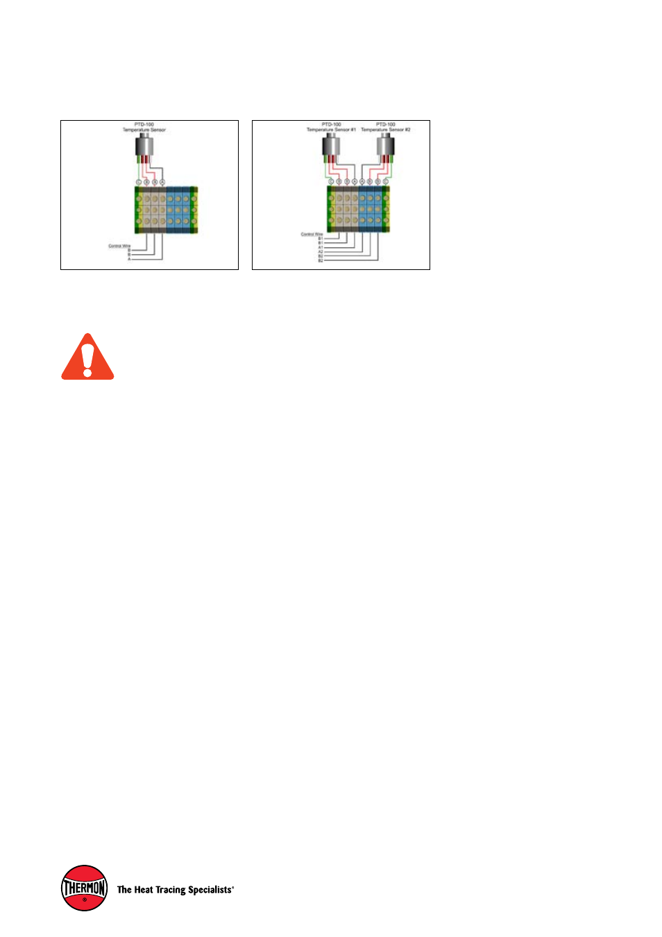
A1.
Control Wire Connection (1 Sensor)
A = White, B = Red, C = Green / Yellow
Wiring Details
Terminator
TM
ZP-PTD100-WP
INSTALLATION PROCEDURES
In order to avoid EMI issues with a temperature control-
ler, the shield of the control wire shall be connected
to the instrumentation earth only. Do not connect the
control wire shield in the junction box.
A2.
Control Wire Connection (2 Sensors)
A = White, B = Red, C = Green / Yellow
See also other documents in the category Thermon Hardware:
- WMK Terminator (4 pages)
- Electric Heat Tracing (12 pages)
- SCTK (5 pages)
- PETK (7 pages)
- ZE-B Beacon Terminator (4 pages)
- ZP-WP Terminator (4 pages)
- ZP-S-WP Terminator (8 pages)
- ZP-XP Terminator (6 pages)
- ZE Terminator (4 pages)
- PETK-3 (5 pages)
- ZL Terminator (7 pages)
- PETK-4 (6 pages)
- HT Heating Module (4 pages)
- MIQ Mineral Insulated Heating Cable v.1 (11 pages)
- MIQ Mineral Insulated Heating Cable v.2 (14 pages)
- ZP-MI-WP Terminator (7 pages)
- ECM-MI-WP Terminator (4 pages)
- ZT-MI-WP Terminator (4 pages)
- ZP-PTD100-XP Terminator (8 pages)
- ZT-P-XP (8 pages)
- ZT-P-WP (8 pages)
- PETK-11 (9 pages)
- ECM-R-XP (8 pages)
- ZP-R-WP (4 pages)
- MI (26 pages)
- ZP-R-XP (4 pages)
- ECM-P-XP (8 pages)
- ECM-R-WP (8 pages)
- ECM-Ambient-WP (4 pages)
- ECM-OS (4 pages)
- SafeTrace Steam Tracers (8 pages)
- TraceNet TCM 18 (96 pages)
- Heat Transfer Compounds (8 pages)
- HeetSheet (4 pages)
- ThermoTube Type SL (4 pages)
- Tubing Bundle v.2 (8 pages)
- ET-6C (2 pages)
- FAK-4L Kit (5 pages)
- TBX-3LC (5 pages)
- ET-7C (4 pages)
- FAK10A-B-C (4 pages)
- FAK-7 (2 pages)
- FAK-9 (4 pages)
- FAK-1 (4 pages)