Terminator, Zt-mi-wp, Installation procedures – Thermon ZT-MI-WP Terminator User Manual
Page 3
3
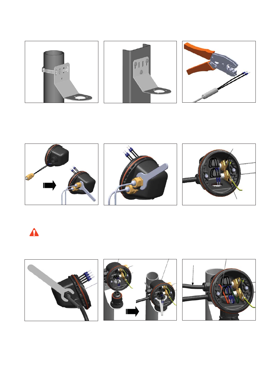
1a.
Mounting Method 1: Secure wall mount
bracket to mounting surface using pipe band
provided with kits.
1b.
Mounting Method 2: Secure wall mount
bracket to mounting surface using customer
supplied screws, fl at washers, and nuts.
Terminator
TM
ZT-MI-WP
INSTALLATION PROCEDURES
4.
Center cold lead sleeve inside cable gland.
Tighten cable glands until ferrule begins to
make contact with cold lead sleeve and cold
lead sleeve cannot be moved by hand. Tighten
cable gland 1/8 additional turn or to a torque
value of 16 Nm (142 lb-in).
6.
Remove M25 dust cap. Install M25 power
gland (customer supplied) in M25 threaded
entry.
2.
Crimp appropriate wire pins (2.5 mm
2
or 6
mm
2
) on MI cable cold lead wires.
3.
Route MI cable cold leads through M20
threaded entries. Screw cable glands into
junction box.
Do not overtighten to ensure o-ring
is not damaged during installation.
CAUTION
7.
Mount junction box base on expediter. Make
sure to align slots to properly orient junction
box base. Tighten nut with Terminator-LN-
Tool. If mounting horizontally, threaded gland
holes must face downward.
8.
Install power cable (if necessary).
5.
Install user supplied M20 Earth Tag and Lock
Nut to threaded M20 Gland.
Earth Tag and Lock Nut
Earth Tag and Lock Nut
Power Cable