Terminator, Ecm-mi-wp, Installation procedures – Thermon ECM-MI-WP Terminator User Manual
Page 2
2
Wire Pins
(per MI cable cold lead,order separately)
12
Terminator
TM
ECM-MI-WP
INSTALLATION PROCEDURES
Kit Contents . . .
1
2
6
4
3
8
5
7
9
Item Quantity
Description
1
1
Expediter Assembly
Support Cap with O-Ring
Threaded Grommet Compressor
Grommet
Support Base with O-Ring
2
1
Junction Box Lid
3
1
Junction Box Base, O-Ring, M25 Dust Cap,
earth plates and ground wires
4
1
Nut
5
1
Banding
6
1
Electronic Control Module w/ Terminal Blocks
(Refer to terminal specifi cations for maximum allowable wire size)
ECM Type
C - Controller
L - Limiter
CL - Controller/Limiter
7
1
Junction Box Lid Cord
8
4
Blind Plug & Lock Nut
9
1
Bracket
10
3
Screws
11
3
Washers
12
2
Wire Pins
Warnings . . .
• Due to the risk of electrical shock, arcing and fi re
caused by product damage or improper usage,
installation or maintenance, a ground-fault protection
device is required.
• Installation must comply with Thermon requirements
(including form PN 50273U for Ex systems) and be
installed in accordance with the regulations as per the
norm EN IEC 60079-14 for hazardous areas (where
applicable), or any other applicable national and local
codes.
• Component approvals and performance ratings are
based on the use of Thermon specifi ed parts only.
• De-energize all power sources before opening
enclosure.
• Avoid electrostatic charge. Clean only with a damp
cloth.
• Keep ends of heating cable and kit components dry
before and during installation.
• Minimum bending radius of heating cable is six (6)
times the cable outer diameter.
• Individuals installing these products are responsible
for complying with all applicable safety and health
guidelines. Proper Personal Protective Equipment
(PPE) should be utilized during installation. Contact
Thermon if you have any additional questions.
The following installation procedures are suggested guidelines
for the installation of the Terminator ECM-MI-WP Kit.
Receiving, Storing and Handling . . .
1. Inspect materials for damage incurred during
shipping.
2. Report damages to the carrier for settlement.
3. Identify parts against the packing list to ensure the
proper type and quantity has been received.
4. Store in a dry location.
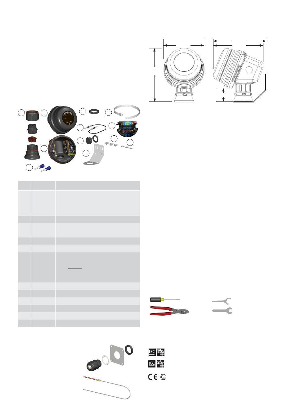
Dimensions . . .
1725
II 2 GD Ex eb mb [ib]ib I
IC T4, Ex tb I
IIC T135°C
S
IRA 12A
TEX5239X
IP66
-60°C ≤
Ta ≤ + 55
°C
IECEx S
IR 12.0103X Ex eb mb [ib]ib I
IC T4, Ex tb I
IIC T135°C
PN 27673
Do
no
t ope
n while energized. See in
sta
llat
ion
in
st
ru
ct
io
ns
.
Te
rm
inator ECM
Fo
r
us
e
as
an
ad
just
able
electronic contro
l m
od
ule
10
11
Tools Required . . .
Terminator-LN-Tool
(order separately)
3 mm
8 mm
28 mm
33 mm
Crimp Tool 2,5mm
2
Order Separately . . .
IEK Insulation Entry Kit (per cable)
IEK-PTD For PTD lead wire
Certifi cations/Approvals . . .
IP66 -60°C Ta +50°C T5, 100°C; -60°C Ta +40°C T6, 85°C
Ordinary & Hazardous Locations
FMG 10.0022X Ex db eb IIC T5-T6, Ex tb IIIC T100°C-T85°C
International Electrotechnical Commission
IEC Certifi cation Scheme for Explosive Atmospheres
SIR 12.0103X
II 2 (2) G Ex eb mb [ib] IIC T4, Ex tb IIIC T135°C SIRA 12ATEX5239X
II 2 (2) D Ex tb IIIC T135°C IP66 Db
190mm
50mm
155mm
206mm
205mm
PTD100 Temperature Sensor