Thermo Technologies Flat Roof User Manual
Page 6
6
(13) Make sure there is no leak in piping system.
(14) Check system pressure and flow rate.
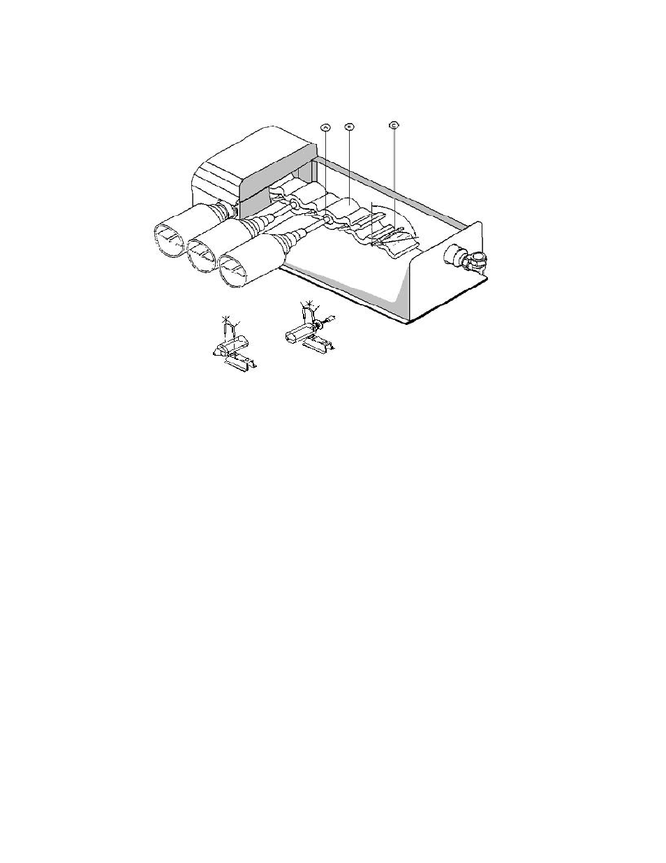
(15) Take -off manifold's lid and remove top layer of insulation from manifold.
(A) With the supplied Stainless steel tube (Key Lever) open the pocket in
the manifold chamber "B" by turning the Key Level "C" through 90
o
. Unpack
the first tube; insert condenser "A" gently through grommet in front of the
manifold. Resting the tube body on the rubber pads of the top and bottom
support rails, slide the condenser "A" into the open pocket. ENSURE BLUE
SURFACE OF ABSORBER FACES UPPERMOST AND TOWARDS THE
SOUTH.
(B) Make sure the tube condenser is exactly between the two copper blocks
and sits evenly through hole in manifold chamber.
(C) Secure tubes by turning the Key Lever to original position.
(D) Set clips over tubes to both top and bottom support rails.
(E) Repeat stages (A), (B), (C), and (D) for all tubes.
(16) Replace top layer of insulation into manifold. Replace manifold's lid and secure with self-
tapping screws.
(17) Make the final inspection on each tube.
(18) Set clips over tubes to both top and bottom support rails.
(19) Switch the pump to control system
The manifold flow and return connections are 3/4" copper pipes. Two compression couplings are
included in each manifold system. These couplings are to be used. Manifold inlet and outlet
should not be sol dered.