Tecfluid LT-ADF User Manual
Page 2
2
!
AMM: Vmax: 250 V
Imax: 3 A
1. Earth
2. Common
3. Normally closed
4. Normally open
AMD: Vnom: 8.2 VDC
Max. level I > 2.2 mA
Min. level I < 1.1 mA
1. Earth
2. Positive
3. Negative
4. Not connected
AMR: Vmax: 250 V
Imax: 0.5 A
1. Earth
2. Common
3. Normally closed
4. Normally open
1
2
3
4
TÉCNICAL DATA
• Material: Metal alloy aluminium without copper
• Ambient temperature range: -20 a 40 ºC
• Ingress protection: IP67
• Category of application : Ex II 2 GD EExd IIC T6
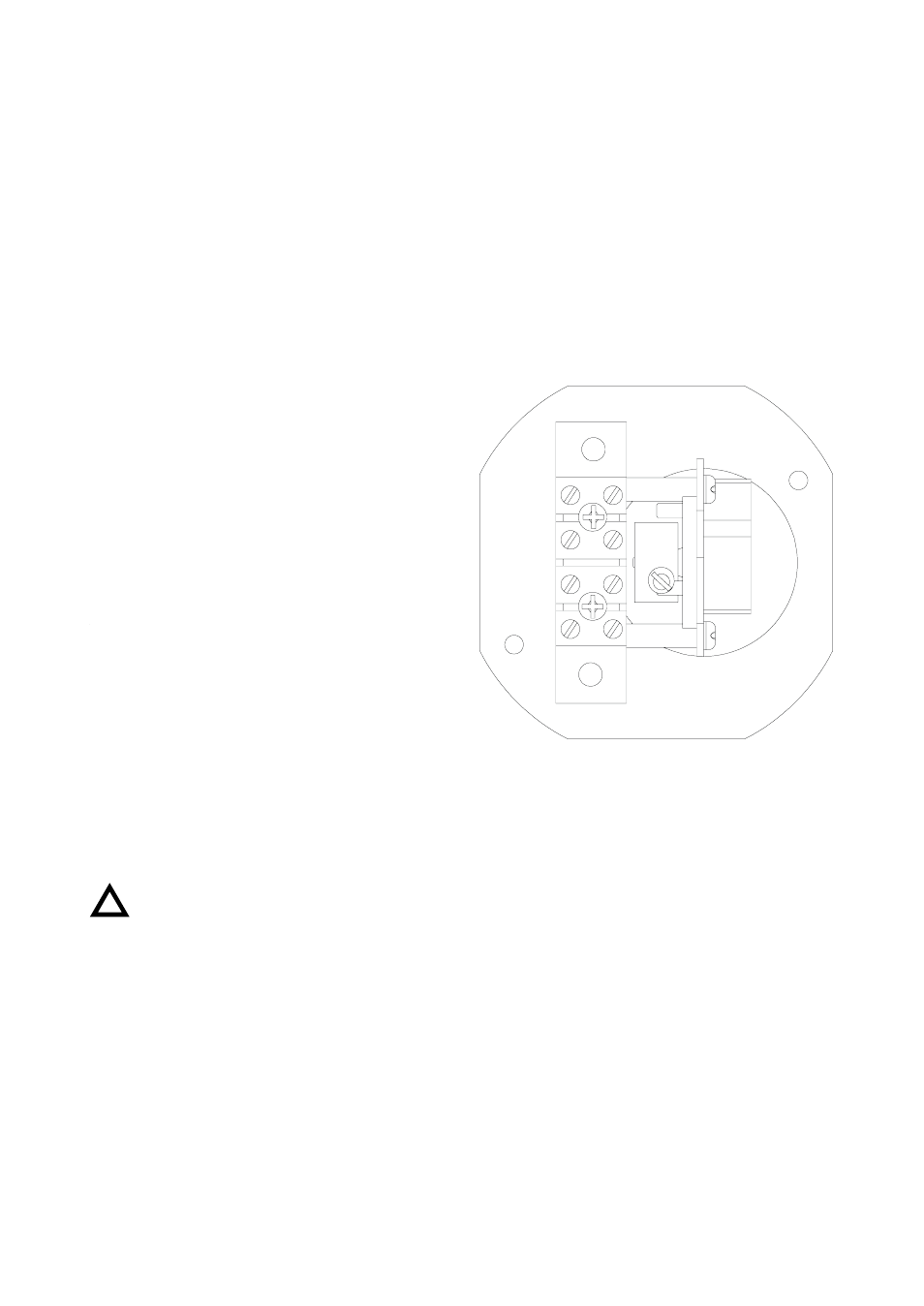
LIMIT SWITCH CHARACTERISTICS AND CONNECTION
Important:
If the operation of the limit switches is checked before installation, this must be done in a non
hazardous area.
To check the limit switch, it must be removed from the level.
Unscrew the electrical housing cover to gain access to the electrical connections.
Situate the limit switch in its normal working position and move a magnet as if it was the float.
The orientation of the magnet varies with the level type. For the LT series (with float in exterior
glass tube) the magnet should be vertical with the north pole must be pointing upwards. For the
LTL (with magnetic strips) series the magnet should be horizontal with the north pole points
towards the level switch.
The signal at the electrical connection terminals will vary according to the float’s position (with the
AMM and AMR this can be checked using a multimeter).
!