Dc b a – Tecfluid AMD For 6000 Series User Manual
Page 3
3
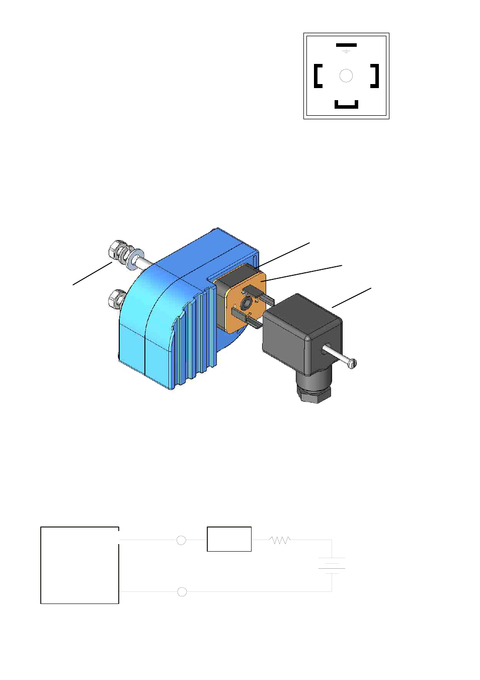
MOUNTING
Once the electrical connection has been made and the cable gland has been tightened, mount the
female connector (A) on the male base (C), placing the seal (B) between the two pieces.
To fix the level switch in its position on the flow meter, remove the nuts and washers (D), mount
the limit switch in the guide as shown on the previous page, assemble the washers and nuts,
situate the limit switch at the required height and tighten the nuts.
In the female connector (A):
Terminal 1:
Negative (Blue sensor cable)
Terminal 2:
Positive (Brown sensor cable)
Terminal 3:
NC
Earth terminal: Earth
3
1
2
If you don’t have the detector, the operation of the amplifier can be checked using the following
circuit diagram:
MAINTENANCE. Electrical verification of the limit switch
a) Check that the voltage at the terminals 1 and 2 is over 7.5 V when the vane is in the slot. Con-
nect a multimeter with the scale in DC mA, in series with the terminal 2.
b) Verify that the current is less than 1 mA when the vane is in the slot, and more than 3 mA when
the vane is out of the slot.
If you don’t have the NAMUR amplifier, the current can be checked using the following circuit dia-
gram:
AMD
+
-
1 k
Ω
+
-
2
1
9V Battery
(8.2V Nominal for
NAMUR )
Multímeter
mA
+
-
D
C
B
A