TE Technology TCA User Manual
Page 16
TE
TECHNOLOGY, INC.
16/22
http://www.tetech.com
email: [email protected]
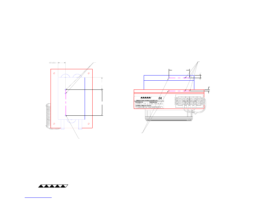
Typical LC-xxx TCA
Typical CP-xxx or AC-xxx TCA
Allowable Locations for Adding Holes for Mounting
Protective Devices
1.
All dimensions in millimeters.
2.
Clamp directly to base of heat sink when adding holes to heat sink; clamp directly to cold side (base of cold sink, cold
plate, or liquid heat exchanger) when adding holes to cold side. Do not apply compressive force from the heat sink to
the cold side.
3.
Locations for protective devices other than those shown here may be acceptable. Contact TE Technology. for
assistance with locating a protective device elsewhere on the TCA.
Notes:
TE
TECHNOLOGY, INC.
USER ADDED HOLES
Ø4 mm MAXIMUM, 9.7 MM DEEP MAXIMUM
DO NOT BREAK THROUGH
SUPPLIED HOLE FOR MOUNTING TEMPERATURE
SENSOR OR OTHER PROTECTIVE DEVICE
25 mm, MINIMUM
AS REQUIRED
AS REQUIRED
SUPPLIED HOLE FOR MOUNTING TEMPERATURE
SENSOR OR OTHER PROTECTIVE DEVICE
(LOCATION MAY VARY)
AS REQUIRED
AS REQUIRED
USER ADDED HOLES
Ø4 mm MAXIMUM,
9.7 MM DEEP MAXIMUM