Super Systems 7EK 31081 User Manual
Page 8
3
TX INPUT
Fig. 5 TX INPUT WIRING
NOTES:
1) Don’t run input wires together with power cables.
2) When shielded cable is used, it should be grounded at
one side only and possibly to the terminal 6 of the
instrument.
3) The impedance of the 20 mA input, is less than 5
W
.
4) The auxiliary power supply (AUX) is rated:
24 V DC (+ 10%), 25 mA maximum.
5) The auxiliary power supply (AUX) is NOT isolated from
measuring input. A duble or reinforced isolation
between instrument input and power line must be
assured by the external transmitter.
B) LOGIC INPUT
Safety note:
1) Do not run logic input wiring together with power
cables.
2) Use an external dry contact capable to switch 0.5 mA,
5 V DC.
3) The instrument needs 100 ms to recognize a contact
status variation.
4) The logic inputs are NOT isolated by the measuring
input. A double or reinforced isolation between logic
inputs and power line must be assured by the external
elements.
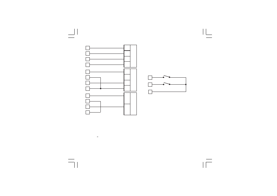
Fig. 6 - LOGIC INPUT WIRING
This instrument is provided with 4 set points (SP, SP2,
SP3 and SP4).
The set point selection is possible only by logic inputs 1
and 2 (terminals 6, 7 and 8).
Logic input 1
Logic input 2
Op. Set point
open (6 - 7)
open (6 - 8)
SP
open (6 - 7)
closed (6 - 8)
SP2
closed (6 - 7)
open (6 - 8)
SP3
closed (6 - 7)
closed (6 - 8)
SP4
3
1
6
5
PWR
+
4-wire
transmitter
OUT
+
OUT
-
PWR
-
IN +
IN -
AUX +
AUX -
3
1
6
5
PWR
+
3-wire
transmitter
OUT
+
GND
IN +
IN -
AUX +
AUX -
3
1
6
5
2-wire
transmitter
OUT
-
OUT
+
IN +
IN -
AUX +
AUX -
8
Log. input 2
7
Log. input 1
6
31081-1-00.p65
3/24/00, 11:59 AM
3