Super Systems 7EK 31080 Calibration Manual User Manual
Page 4
4
The "PH" calibration is correct if the indication is equal to "P. 3
0000" + 10 counts.
1) Check the zero calibration, by making the short circuit as
described at point C.1, the read-out must be equal to "P. 0 0000"
+ 10 counts.
2) Remove the short circuit.
3) Connect the calibrator as shown in Fig. 7.
4) Check the linearity by setting the calibrator to 125.00 Ω. The
read-out must be "P. 1 0190" + 10 counts.
5) Set the calibrator to 250.00 Ω. The read-out must be "P. 2
0189" + 10 counts.
6) Push FUNC pushbutton, the instrument will go to the next
calibration group.
D) mA INPUT CALIBRATION
D.1) "nAL" - INITIAL SCALE VALUE
The lower display will show "nAL" while the upper display will show
"OFF"
1) Make the specific hardware setting as described at paragraph 2.
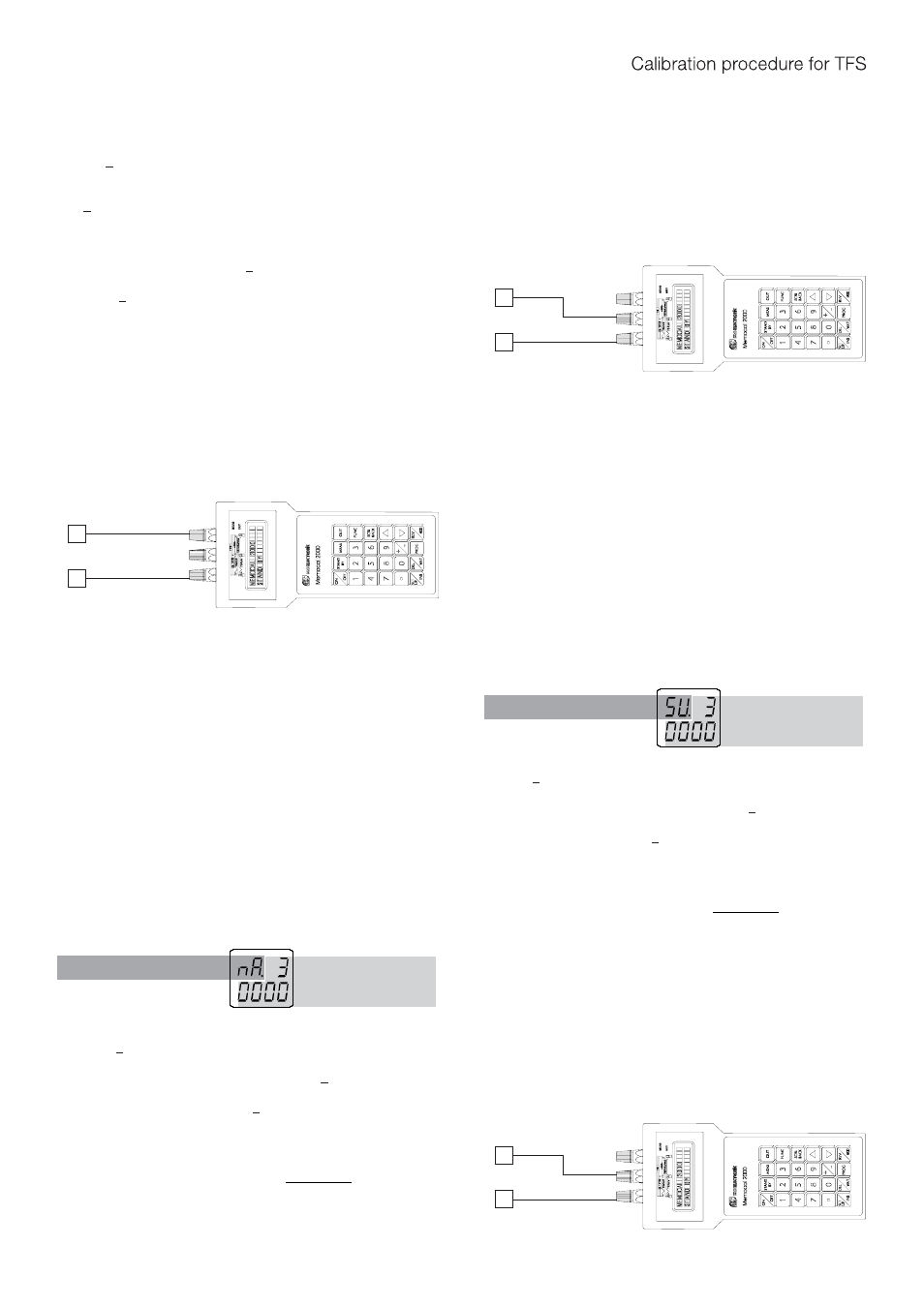
2) Connect the instrument under test to the calibrator as shown in
Fig. 6.
Fig. 6
3) Set calibrator to 0.000 mA.
4) Push ▲or ▼ pushbutton, the upper display will change to "On".
5) After a few seconds, start the calibration by pushing FUNC
pushbutton. At the end of this calibration routine, the instrument
will go to the next step.
D.2) "nAH" - FINAL SCALE VALUE
The lower display will show "nAH" while the upper display will show
"OFF"
1) Set the calibrator to 20.000 mA.
2) Push ▲ or ▼ pushbutton, the upper display will change to "On".
3) After a few seconds, start the calibration by pushing FUNC
pushbutton. At the end of this calibration routine, the instrument
will go to the next step.
D.3) "nA." - mA INPUT CHECK
The upper and lower show "nA." followed by the measured value in
counts.
The "nAH" calibration is correct if the indication is equal to "nA.
3 0000" + 10 counts.
1) Check the zero calibration, by setting the calibrator to 0.000 mA,
the read-out must be equal to "nA. 0 0000" + 10 counts.
2) Check the linearity by setting the calibrator to 10.000 mA , the
read-out must be "nA. 1 5000" + 10 counts.
NOTE: when it is desired to use a different check point, the
following formula describes the ratio between the signal input
and the instrument read-out (in counts).
Instrument readout (in counts) = input value
20 (mA)
30000
•
3) Push FUNC pushbutton, the instrument will go to the next
calibration group.
E) 5 V INPUT CALIBRATION
E.1) "5UL" - INITIAL SCALE VALUE
The lower display will show "5UL" while the upper display will show
"OFF"
1) Make the specific hardware setting as described at paragraph 2.
2) Connect the instrument under test to the calibrator as shown in
Fig. 7.
Fig.7
3) Set calibrator to 0.000 V.
4) Push ▲ or ▼ pushbutton, the upper display will change to "On".
5) After a few seconds, start the calibration by pushing FUNC
pushbutton. At the end of this calibration routine, the instrument
will go to the next step.
E.2) "5UH" - FINAL SCALE VALUE
The lower display will show "5UH" while the upper display will show
"OFF"
1) Set the calibrator to 5.000 V.
2) Push ▲ or ▼ pushbutton, the upper display will change to "On".
3) After a few seconds, start the calibration by pushing FUNC
pushbutton. At the end of this calibration routine, the instrument
will go to the next step.
E.3) "5U." - 5 V INPUT CHECK
The upper and the lower displays show "5U." followed by the
measured value in counts.
The "5UH" calibration is correct if the indication is equal to "5U. 3
0000" + 10 counts.
1) Check the zero calibration, by setting the calibrator to 0.0000 V,
the read-out must be equal to "5U. 0 0000" + 10 counts.
2) Check the linearity by setting the calibrator to 2.500 V The read-
out must be "5U. 1 5000" + 10 counts.
NOTE: when it is desired to use a different check point, the
following formula describes the ratio between the signal input
and the instrument read-out (in counts).
Instrument readout (in counts) = input value
5 (V)
30000
•
3) Push FUNC pushbutton, the instrument will go to the next
calibration group.
F) 10 V INPUT CALIBRATION
F.1) "10UL" - INITIAL SCALE VALUE
The lower display will show "10UL" while the upper display will
show "OFF"
1) Make the specific hardware setting as described at paragraph 2.
2) Connect the instrument under test to the calibrator as shown in
Fig. 8.
Fig.8
1
_
+
3
1
_
+
3
1
_
+
3
Check symbol
Measured or generated
value (in counts)
Check symbol
Measured or generated
value (in counts)