Programmable clock divider – Sundance SMT356 User Manual
Page 8
Version 2.1
Page 8 of 26
SMT356356 User Manual
D31-24 determines the number of samples in clock enable mode ‘0’. The range is
from 1-256. The value loaded into bits 31-24 is the required sample count –1. A value
of 0 gives 1 sample, a value of 0xFF gives 256 samples.
Note that the sample count should be changed before the acquisition is triggered.
Bits D15-8 control the enabled state of the 8 ADCs. The power-on state is a ‘1’ for
each bit, indicating that all channels are enabled. Setting a bit to a ‘0’ will remove that
ADC’s output from appearing in the SDB data stream.
Programmable Clock Divider
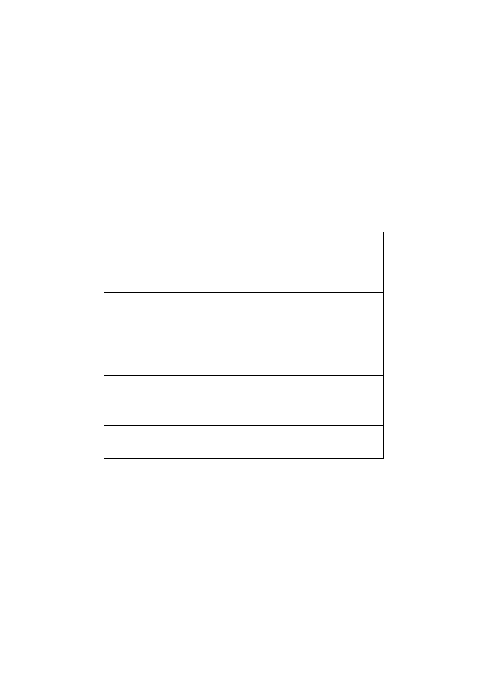
An 8-bit divider is provided which allows the ADC clock to be provided from a divided
clock. The following table shows the possible values,
Divider Value
ADC Sample
Frequency (MHz)
[Internal clock]
Division
[External clock]
00
50
2
01
25
4
02
16.6
6
03
12.5
8
04 10 10
05 8.3 12
06 7.1 14
07 6.3 16
08 5.5 18
09 5 20
…
Sampling rates of 50, 25, 16.6 and 12.5 are not allowed.