Sundance FC203A User Manual
Page 6
Page 6 of 6
Revision 0.5
Sundance Digital Signal Processing Inc.
4790 Caughlin Parkway 233, Reno, NV 89519-0907, U.S.A.
Tel: +1 (775) 827-3103, Fax: +1 (775) 827-3664, email:
www.sundancedsp.com
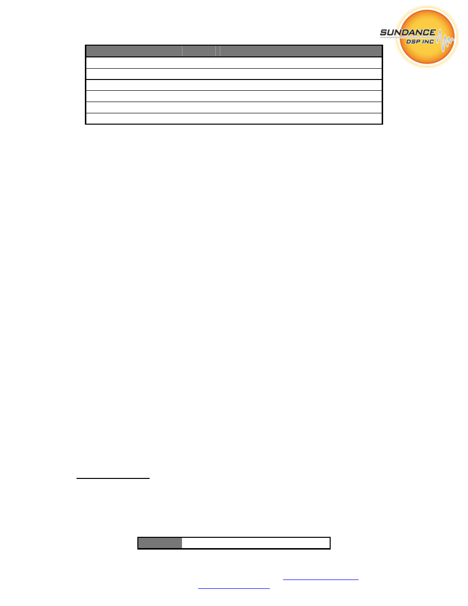
Signal
Bits
Mode Description
m
3..lsb
R/W
Configure m for input streams
LOW_FREQ 15..4
R/W
Select lowest frequency bin
SPAN
25..16
R/W
Select number of active frequency bins
EXCHANGE 26
R/W
Enable high/low exchange
RESERVED
27 R/W
Pass-through
(reserved)
ENABLE msb..28
R/W
Output/function
enable
Table 2 - FC203A Control Word
The FC203A sub-component ignores some of the bits in the control word; they exist to enable
the configuration of multiple modules (including FC203B) in a daisy-chain manner.
‘m’ determines the number of raw frequency component samples that are accepted at the Ix_IN
and Qx_IN ports to make up one frame. The relation between the frame size M and the control
word value ‘m’ is M=2
m
. After M samples are received on each input the internal count of bin
number is reset to zero. The maximum value of m is 12, corresponding to 4096 samples per
frame.
LOW_FREQ determines the frequency bin offset (from 0) which determines the start of the
spectral sampling on each of the input samples. All bins up to but not including LOW_FREQ are
discarded. If LOW_FREQ is zero, then no samples are discarded initially.
SPAN determines the number of frequency bins that will be passed along to each of the FC203A
outputs. Both F0_OUT and F1_OUT will receive SPAN samples on each frame. LOW_FREQ
+ 2 * SPAN must be less than M or the results will be undefined. SPAN is ten bits in size, a
value of zero indicates the maximum 1024 samples will be passed.
EXCHANGE determines if a spectral exchange of the low vs. high frequencies will be
performed on the streams. Low frequency bins are in the range [LOW_FREQ, LOW_FREQ +
SPAN – 1]. High frequency bins are in the range [LOW_FREQ + SPAN, LOW_FREQ + 2 *
SPAN – 1]. If EXCHANGE is zero, the low-frequency bins are passed to F0_OUT. If
EXCHANGE is one, the low-frequency bins are passed to F1_OUT.
ENABLE will cause the module to generate data on its output (F0_OUT, F1_OUT) ports if any
of the four bits are non-zero.
NOTE: To simplify the FPGA logic, the control word is assumed to be static while the module is
enabled. Changes to m, LOW_FREQ, SPAN, or EXCHANGE while any ENABLE bit is set may
result in unpredictable output.
F0_OUT, F1_OUT
These are dual-channel partitioned frequency data ports. Data values are groups of 64-bit values
in bursts of SPAN qwords. The 64-bit values consist of the in-phase and quadrature components
(16-bit two’s complement as described in the FC108 User Manual) of two channels. This port is
suitable for connecting to the Fx_IN ports of the FC203B subcomponent.
Bit 15..0
I0(0) I0(1) … I0(SPAN
–
1)