4 functional description, 1 block diagram – Sundance SMT111 User Manual
Page 8
User Manual SMT111
Page 8 of 18
Last Edited: 21/05/2010 16:53:00
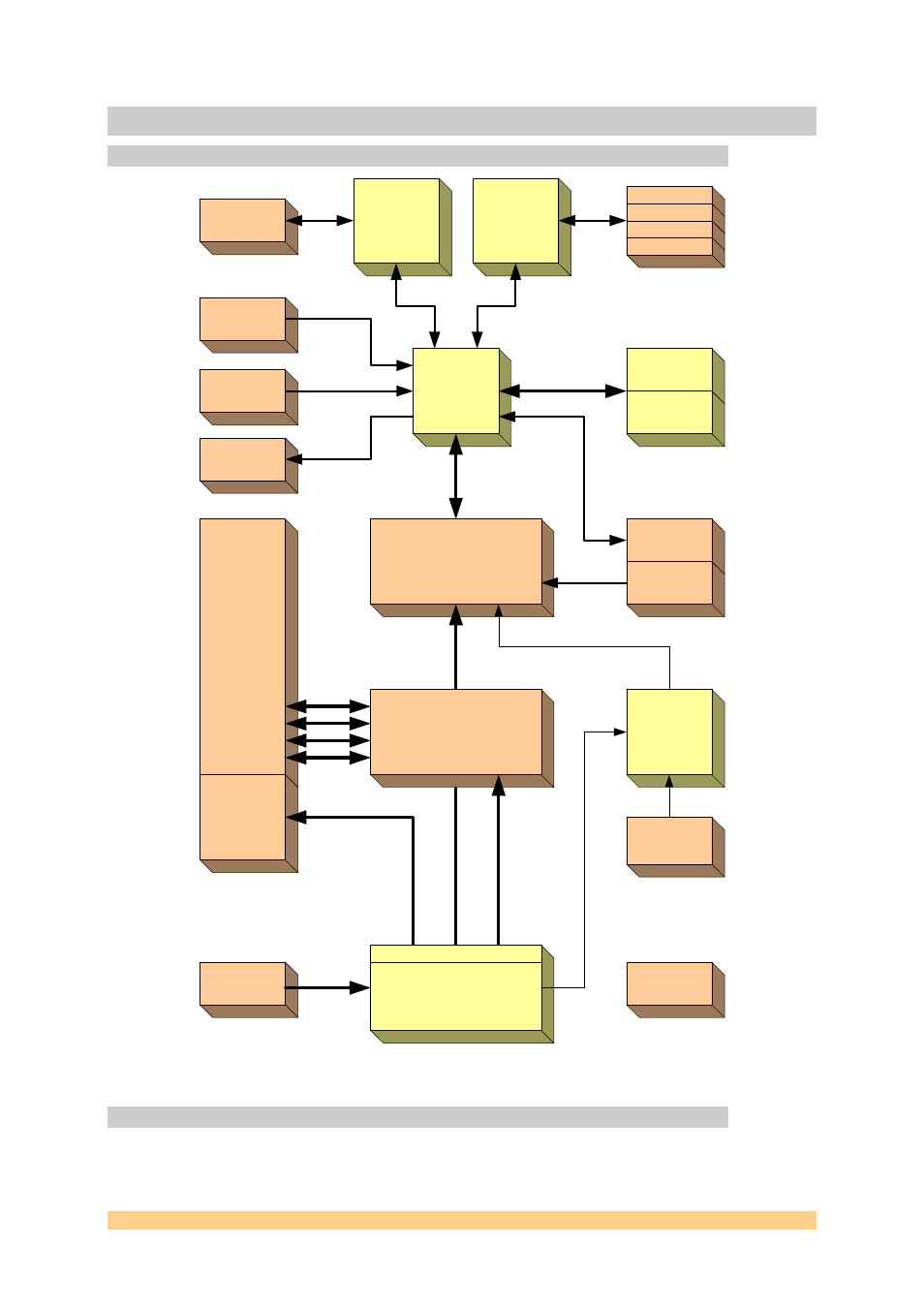
4 Functional Description
4.1 Block Diagram
SLB
FPGA
Spartan-3
Primary
TIM Connector
SLB
Power
Flash
Memory
64MBytes
USB2
Controller
JTAG
Programming
Header
JTAG Out
TTL I/O
JTAG In
USB
Connector
Power Converters
12Vdc
Input
Secondary
TIM Connector
+/-12V, +5V, +3.3V
Reset
Control
Reset
Switch
User
LEDs
CP0 & 3
CP
1,
2,
4
,5
Quad
UART
RS232
RS232
RS232
RS232
microSD
socket
DIP
switch
RSL
Pass-through
Connector
Figure 1: SMT111 - Block Diagram
See also other documents in the category Sundance Equipment:
- SMT107 (16 pages)
- SMT6035 v.2.2 (39 pages)
- SMT6012 v.4.6 (22 pages)
- FC100 (12 pages)
- FC108 v.1.1 (10 pages)
- SMT6065 v.4.0 (45 pages)
- FFT v.2.1 (19 pages)
- SMT118LT (10 pages)
- SMT118 (20 pages)
- SMT123-SHB (13 pages)
- SMT128 (15 pages)
- SMT145 (18 pages)
- SMT148 (35 pages)
- SMT130 v.1.0 (46 pages)
- SMT148FX (48 pages)
- SMT310Q (55 pages)
- PARS (70 pages)
- SMT166-FMC (52 pages)
- SMT166 (44 pages)
- SMT300Q v.1.6 (61 pages)
- SMT310 v.1.6 (50 pages)
- SMT317 (24 pages)
- SMT326v2 (24 pages)
- SMT338 (19 pages)
- SMT349 (32 pages)
- SMT339 v.1.3 (27 pages)
- SMT338-VP (22 pages)
- SMT358 (25 pages)
- SMT351T (37 pages)
- SMT351 (25 pages)
- SMT350 (45 pages)
- SMT362 (30 pages)
- SMT365G (23 pages)
- SMT364 (37 pages)
- SMT373 (15 pages)
- SMT368 (24 pages)
- SMT370v3 (46 pages)
- SMT377 (22 pages)
- SMT381 2007 (31 pages)
- SMT381-VP (81 pages)
- SMT387 (42 pages)
- SMT391 (18 pages)
- SMT384 (47 pages)
- SMT390-VP (55 pages)