5 wiring, Chart 1 – Sun Pumps SCP 48-18-48Y BC User Manual
Page 9
3.5 Wiring
Prior to connecting any wires to the controller, be sure you have a system wiring diagram to use as a reference (See
Figure 2, 3 & 4). Guessing at polarity and connection points is not worth the risk of potential product damage and/or
personal injury. Use copper conductors only. Flexible metal liquid-tight conduit and appropriate liquid-tight
connectors should be used for all wiring, into, out of, and between electrical enclosures. The PV In and Pump Out
connectors use the 1” holes to the front of the controller and the ½” holes are for auxiliary connections for the remote
switch and low water sensor circuits. The provided plugs for unused holes are Heyco PG threaded plugs for standard
½” threaded holes. Plugs must be installed in order to weather proof the controller and prevent shock hazards.
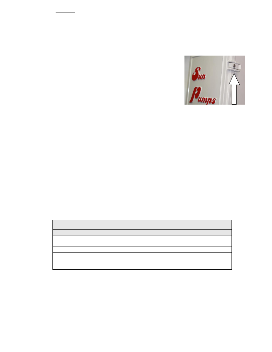
The PC series controllers have a locking screw to prevent tampering. In order to open the box this screw must be
removed. Using a #2 Philips screwdriver, turning it left will loosen it and turning right will tighten it. Do not over
tighten this screw it is only meant to hold the latch in place. If the screw is lost SunPumps, Inc. recommends replacing
it with a stainless steel pan head Philips #8 – 32 X 3/8” screw.
Ensure the wire sizes are of adequate diameter (gauge) to minimize voltage drop. Please refer to a DC voltage loss
table or call your SunPumps dealer for assistance. Minimum wire size for PV interconnects is 12 AWG, minimum
wire size for the combiner box or disconnect connection to the controller and the controller to the pump motor is 10
AWG. Insufficient wire gauge will cause excessive voltage losses to the motor and will reduce the flow rate of the
pump
. A solid copper bonding wire, no smaller than 8 AWG (8.4mm2), shall be connected from the motor ground to all
metal part of the swimming pool, spa or hot tub. Wire may be rated for 60° C, 60°/75° C or 75° C. The brushless DC motor
frame must be grounded to the control box.
All other system equipment should be installed before proceeding with wiring the controller. A fused combiner box or
disconnect switch should be installed between the solar array and the PC series controller. SunPumps recommends an
MNPV 6 for systems with 3 or 4 solar arrays in parallel or an MNPV 3 for systems with 1 or 2 solar arrays in parallel
along with the appropriately rated MNDC breakers or MNTS fuse holders with appropriate MNFUSE fuses rated to
be the lowest fuse which will allow for the short circuit current rating of your solar panels. Alternatively for systems
with a single solar array, 30A NEMA 3R fused disconnects may be used with appropriate fuses. Double check
polarity and wire termination tightness before powering up the system.
CAUTION: Photovoltaic panels produce DC electricity when exposed to sunlight. Cover the panels with a
blanket or with a non-opaque material before wiring. Install a disconnect switch between the solar modules
and the controller.
Chart 1
Controller Model No.
Max
Nominal
Min Supply Wire
Size, Cu
Overcurrent
Current (A)
Voltage (V)
60°C
75°C
Protection, Amps
PCA-60BLS-M2
14
48
– 60
12
12
20
PCA-120BLS-M2
12
60
– 120
12
12
20
PCC-48BLS-M2
40
48
– 52
8
6
50
PCC-120BLS-M2
12.5
90
– 120
12
12
20
PCC-180BLS-M2
12.5
120
– 180
12
12
20
PCC-240BLS-M2
12.5
180
– 240
12
12
20
- SCP 100-60-180 BV SCP 115-60-240 BV SCP 50-50-120 BC SCP 58-51-48 BC SCP 62-42-105 BC SCP 67-50-120 BC SCP 75-40-105 BC SCP 80-55-180 BC SCP 86-55-180 BV SCP 86-65-180 BC SCP 94-37-120 BV MTR BLM-SB-103S-120Y MTR BLM-SB-203S-180 MTR BLM-SB-303S-240 PCC-120BLS-M2 PCC-180BLS-M2 PCC-240BLS-M2 MTR-BLM-SF-153C-120 MTR-BLM-SF-153C-90Y MTR-BLM-SF-303C-180 MTR-BLM-SF-353C-240 MTR-BLM-SF-153J-120 MTR-BLM-SF-153J-90Y MTR-BLM-SF-303J-180 MTR-BLM-SF-353J-240 PCA-120-BLS-M2 PCA-60-BLS-M2 MTR BLM-SB-073S-60 MTR BLM-SB-153S-120 SCS 10-165-60 BL SCS 10-600-240 BL SCS 14-95-60 BL SCS 18-90-60 BL SCS 7-210-60 BL