Studio Technologies 93 User Manual
Page 12
Issue 1, January 2008
Model 93 User Guide
Page 12
Studio Technologies, Inc.
W1 and XLR cables. Pin mode is only avail-
able in the W1 to W1 and XLR to XLR cable
modes. It is not offered with the other two
cable modes as it’s not appropriate for use
with W1 “fanouts.”
In the channel mode W1 testing is orga-
nized as twelve 3-conductor groups. The
3-conductors consist of a shield and a sig-
nal pair. In standard W1 cable assemblies
these twelve channels are wired using 36
pins of 39 provided on W1 connectors;
pins r, m, and k are generally not used.
The pin mode is provided so that a detailed
view of the signal paths associated with a
cable assembly can be obtained. In the pin
mode testing can be performed on all 39
pins of a W1 connector associated with a
W1 assembly, although pins r, m, and k are
tested as a group. Pin mode is useful when
fabricating new W1 assemblies or repairing
cable assemblies which the channel mode
has identified as being defective.
The button located to the left of the down
arrow is used to select between channel
mode and pin mode. Pressing and holding
this button for two seconds will cause the
mode to change between channel mode
and pin mode, or vice-versa. As previously
discussed, only when the cable mode is
selected for W1 to W1 or XLR to XLR is it
possible to select pin mode. The indicator
light associated with the active cable mode
is used to display whether channel mode or
pin mode is selected. When channel mode
is selected the light is lit steadily. The light
will flash to indicate that pin mode is select-
ed. The selected mode, channel or pin, will
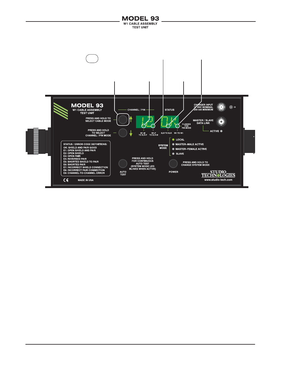
Fanout:
W1 male to
XLR female
Figure 4. Model 93 Configuration—Cable Modes
Fanout:
W1 female
to XLR male
XLR to XLR
W1 to W1
Press and hold
“up” button to
cycle through
cable modes.