Audio outputs, Dc input and data bus, Mounting – Studio Technologies 5132 2014 User Manual
Page 9
Model 5132 User Guide
Issue 5, October 2014
Studio Technologies, Inc.
Page 9
Model 5132
Party-Line Interface Module
Audio Outputs
Associated with each of the Model 5132’s
two party-line interface channels is a bal-
anced (differential), line-level analog audio
output. The circuitry is electronically bal-
anced and capacitor coupled. The nominal
output level of a Model 5132S (SMPTE)
version module is +4 dBu with a maximum
output level of +24 dBu. The nominal level
of a Model 5132E (EBU) version module is
0 dBu with a maximum level of +18 dBu.
Connections to the audio outputs are
made using a 5-position header connector
located on the Model 5132’s rear-most
circuit board. For details on appropriate
mating connectors refer to Appendix A
located at the end of this document.
For connection to balanced inputs on
related equipment the signal + (high) and
signal – (low) connections should be used.
Pin 1, common/shield, may or may not
need to be connected as dictated by the
specific installation. Refer to Figure 3 for
details.
When interfacing the outputs to unbal-
anced inputs on associated equipment
connect only to the Model 5132’s signal
+ (high) and common/shield. Do not make
any connections to the Model 5132’s
– (low) terminals.
DC Input and Data Bus
A 4-position header, located adjacent to
the audio input and output headers, is
used to connect DC power and the RS-485
data bus to the Model 5132. For details on
appropriate mating connectors refer to
Appendix A located at the end of this
document.
A source of nominal 12 volts DC, with an
acceptable range of 10 to 18, is required
for Model 5132 operation. The maximum
current is 800 mA at 12 volts DC.
For remote control operation an RS-485
data bus connection from a Studio Tech-
nologies’ Model 5190 Remote Access
Module is required. Most applications will
only have the DC power connections im-
plemented so these two pins will typically
remain unconnected. Refer to Figure 4
for details.
Mounting
The Model 5132 is intended for mount-
ing into an installation-specific enclosure
or rack panel. Refer to Appendix B for the
unit’s dimensions and mounting screw
locations. Please contact the factory to
discuss mounting options.
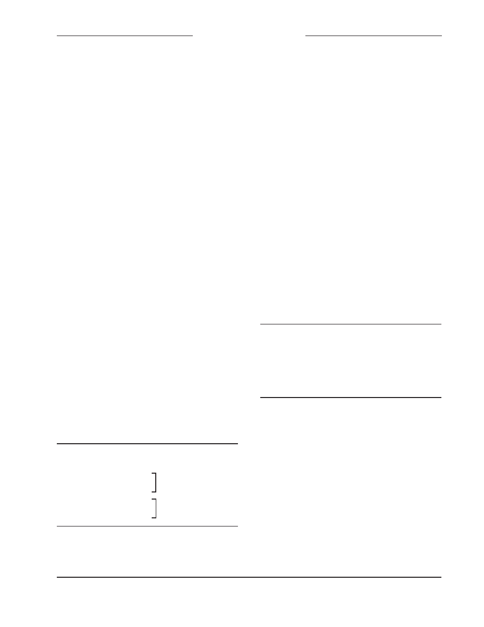
Pin Number
Function
1
Common/Shield
2
+
3
–
4
+
5
–
Figure 3. Audio Outputs
Pin Number
Function
1
– DC (Common)
2
+ DC (10-18 volts)
3
+ Data (RS-485)
4
– Data (RS-485)
Figure 4. DC Input and Data Bus Connections
Channel 1
Channel 2