Configuration, Operation, Rs-485 address – Studio Technologies 5132 2014 User Manual
Page 10: Party-line power
Issue 5, October 2014
Model 5132 User Guide
Page 10
Studio Technologies, Inc.
Model 5132
Party-Line Interface Module
Configuration
RS-485 Address
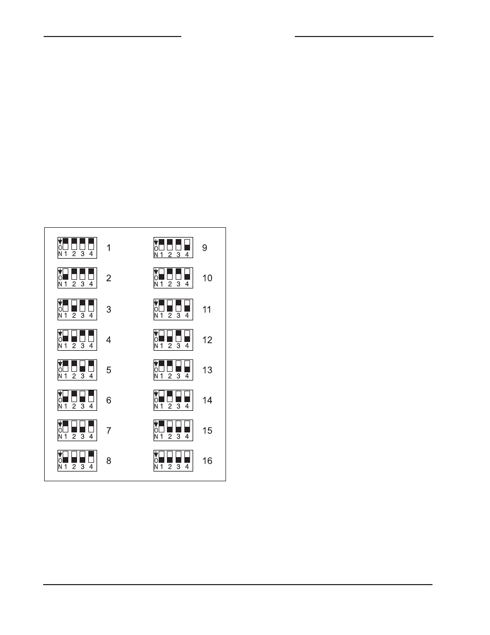
One configuration setting must be per-
formed for applications that implement re-
mote control of Model 5132 functions. While
up to 16 Model 5100-Series modules can
“share” the RS-485 data bus, each mod-
ule must have a unique address. Selecting
the device’s address involves setting four
configuration switches. Refer to Figure 5 for
details.
pushbutton switches allow the user to se-
lect the on/off status of the internal party-
line power source as well as activating
the auto null function. Depending on how
the Model 5132 is to be used the internal
party-line power source can be enabled
or disabled. It would be enabled whenever
user beltpacks are going to be the only
devices connected directly to the Model
5132. The internal power source should
be turned off whenever the Model 5132 is
going to be connected to an existing party-
line intercom circuit that includes power
and audio terminations.
The auto null function is used whenever
significant changes are made to the num-
ber of user devices or the interface cabling
connected to the party-line interface. It
should also be used if the characteristics
of a connected party-line intercom circuit
change. Activating the auto null function is
simple, only requiring the pressing of the
Auto Null pushbutton switch.
Maintaining the correct levels coming from
the line-level audio sources is very impor-
tant. This will ensure that proper signal lev-
els are presented to party-line users and
that optimal audio fidelity is maintained.
The audio level meters, PL Power (+28V)
LED, and Pin 2 Status LED will assist us-
ers in confirming that correct operation is
taking place. In addition, the under-voltage
shut-down function will help to protect the
internal party-line power supply should a
fault condition be detected.
Party-Line Power
A pushbutton switch and status LED are
associated with the Model 5132’s internal
party-line power source. A momentarily
press of the PL Power (+28V) pushbutton
will “toggle” (alternate) between the power
Figure 5. RS-485 Address Settings
Operation
The Model 5132 is designed for continu-
ous operation with no internal adjustment,
calibration, or maintenance required. Two