Operation, Mic/line inputs – Studio Technologies 742A User Manual
Page 18
Issue 1, July 2012
Model 742A User Guide
Page 18
Studio Technologies, Inc.
Audio Mixer
Operation
While the Model 742A Audio Mixer is quite
simple to operate, there are nuances in
its design that make a detailed discussion
worthwhile. We’ll start with the individual
sections that make up the Model 742A, then
we’ll review how the sections work together
to become your audio “master control.”
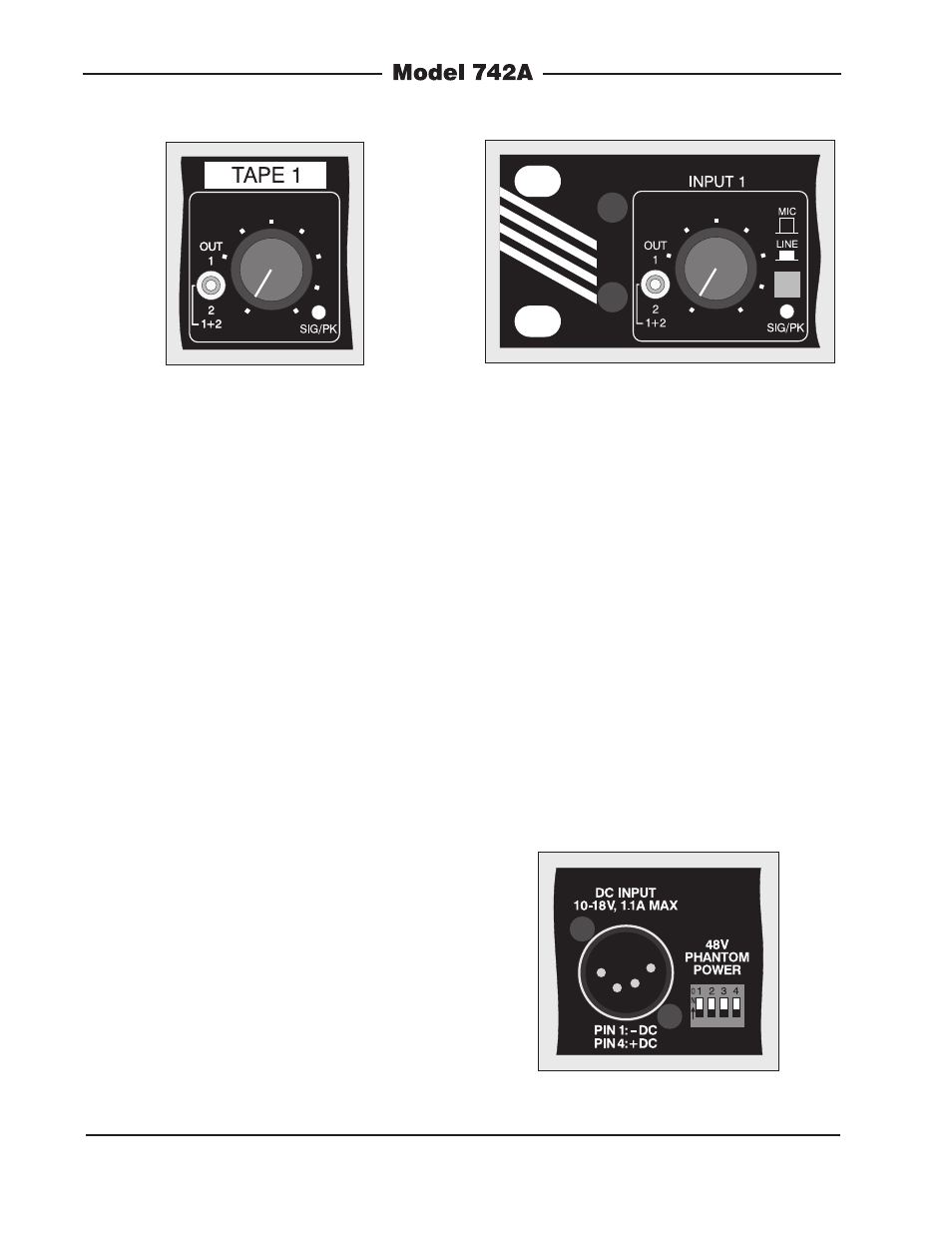
Mic/Line Inputs
Four identical mic/line input channels are
provided, each being compatible with mi-
crophone and line-level signals. (Refer to
Figure 12 for a detailed view of one of the
mic/line input channel sections.) The follow-
ing provides a detailed description of one
of the mic/line inputs:
Input Sensitivity
The input circuitry is compatible with a wide
range of signal levels, as well as being
protected from overload. The mic/line push-
button is used to select the sensitivity of the
input. In the mic (out) position, the expected
nominal input level range is –55 to –35 dBu.
In the line (in) position, a 44 dB pad is in-
serted into the circuit, making the expected
nominal input level range –12 to +8 dBu.
Phantom Power
In most broadcast news and general-
audio applications, phantom-powered
condenser microphones are not utilized.
However, this is not always the situation
and the Model 742A does allow 48 volt
phantom power to be supplied to the four
mic/line input channels. Four DIP switch-
es, accessible on the back panel, allow
+48 volt phantom power to be individually
selected for each mic/line input. The label-
ing on the DIP switches, 1 through 4, cor-
responds with the mic/line input channels.
Placing a switch in its on (up) position
enables phantom power for its respective
channel. (Refer to Figure 13 for a detailed
view.)
Figure 11. Detail of front panel showing
installation-specific labeling
Figure 12. Detail of front panel showing one
mic/line input channel (typical of four)
Figure 13. Detail of back panel showing the +48
volt phantom power DIP switch