Monitor outputs – Studio Technologies 742A User Manual
Page 13
Model 742A User Guide
Issue 1, July 2012
Studio Technologies, Inc.
Page 13
Audio Mixer
will drop slightly. A 0.5 dB difference in
output level can be expected as the load
impedance changes from 10 k ohms to
600 ohms. This loading situation applies
to the monitor outputs and reference tone
direct outputs as well.
Note that the main outputs are intended
only for connection to devices located
within a broadcast vehicle or dedicated
indoor facility. While the circuitry used in
the outputs is robust and sonically excel-
lent, they’re not intended for direct expo-
sure to the extreme conditions that can
occur in the nasty “outside world.” This
limitation is normally not an issue as the
main outputs will typically be connected
to inputs on a distribution amplifier. Should
the main outputs need to be connected
directly to a vehicle’s I/O panel, it’s recom-
mended that one-to-one isolation trans-
formers be placed in their signal paths.
Ensure that any transformer selected is
specified for use in line-level, rather than
just microphone-level, applications.
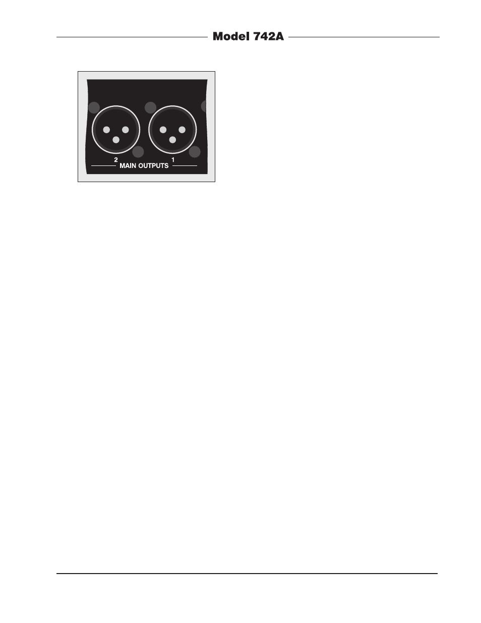
The main outputs utilize 3-pin male XLR
connectors for interconnection. Prepare
the mating connectors (females) so that
pin 2 is signal high (+ or hot), pin 3 is low
(– or cold), and pin 1 is shield. Whether
these outputs are wired via a patch bay
will depend on the specific installation. But
at least having “mults” of the main outputs
on patch points is probably a good idea.
While balanced operation is generally
preferred, unbalanced operation is not
a problem for the output circuitry. To con-
nect to unbalanced loads prepare the
mating connectors so that pin 2 is high
(+ or hot), and both pins 1 and 3 are
shield. For optimal unbalanced opera-
tion, it is important to connect pins 1 and
3 together directly on the connector that
mates with the Model 742A, not at the
other end of the cable.
Monitor Outputs
The monitor outputs are designed to
connect to a variety of devices. In some
applications they will connect to an audio
power amplifier associated with a set of
monitor loudspeakers. In mobile applica-
tions it’s popular to use loudspeakers with
an internal amplifier, such as those from
Fostex. And, depending on how the moni-
tor outputs are internally configured, they
can also serve as a second set of +4 dBu
nominal main outputs.
The monitor outputs are electronically bal-
anced, capacitor coupled, and line-level.
They can drive balanced or unbalanced
loads of 600 ohms or greater. Configura-
tion jumpers allow the monitor outputs
to be set from among three operating
modes. In the “post” mode the output lev-
els are dependent upon the settings of the
front-panel level controls. In the “pre –10”
mode the monitor outputs have a fixed
nominal output level of –10 dBu. In this
mode, the nominal output level has been
optimized to match the input sensitivity
typically found on amplified loudspeakers.
Figure 5. Detail of back panel
showing main output connectors