Studio Technologies 742A User Manual
Page 16
Issue 1, July 2012
Model 742A User Guide
Page 16
Studio Technologies, Inc.
Audio Mixer
below the tone function’s on/off switch
on the front panel. (Refer to Figure 9 for a
detailed view.)
standard and should be familiar to many
technical personnel.
Because the Model 742A contains no
power on/off switch it will begin operation
as soon as a DC power source is connect-
ed. To confirm that the Model 742A
is operating the LED indicator labeled
PWR/TONE will light. This LED is located
below the tone function’s on/off switch on
the front panel. (Refer to Figure 9 for
a detailed view.)
As previously mentioned, both an AC
mains source and a DC source can be
connected at the same time. If this is the
configuration then the AC mains source
will always power the Model 742A with
the DC source serving as a “hot standby.”
Only if the AC source fails will the unit
draw power from the DC source. This will
occur automatically with no interruption
of Model 742A operation. There should
be no problem with a battery being con-
nected as a standby power source. In this
“backup” mode there will be no continu-
ous current draw that will significantly
discharge it. This is because the Model
742A draws less that 100 microamperes
(uA) from the DC input when an AC mains
source is connected.
Figure 9. Detail of front panel showing the
power/tone LED indicator
Safety Warning: The Model 742A
does not contain an AC mains discon-
nect switch. As such, the AC mains
cord plug serves as the disconnection
device. Safety considerations require
that the plug and associated inlet
be easily accessible to allow rapid
disconnection of AC mains power
should it prove necessary.
Connecting DC Power
The Model 742A can also operate from a
source of 10 to 18 volts DC. The current
required from a 12 volt DC source is 0.9
ampere maximum. (A source of 10 volts
DC needs to supply 1.1 amperes maxi-
mum.) A 4-pin male XLR connector, lo-
cated on the unit’s back panel, is used to
connect the source of DC. (Refer to Figure
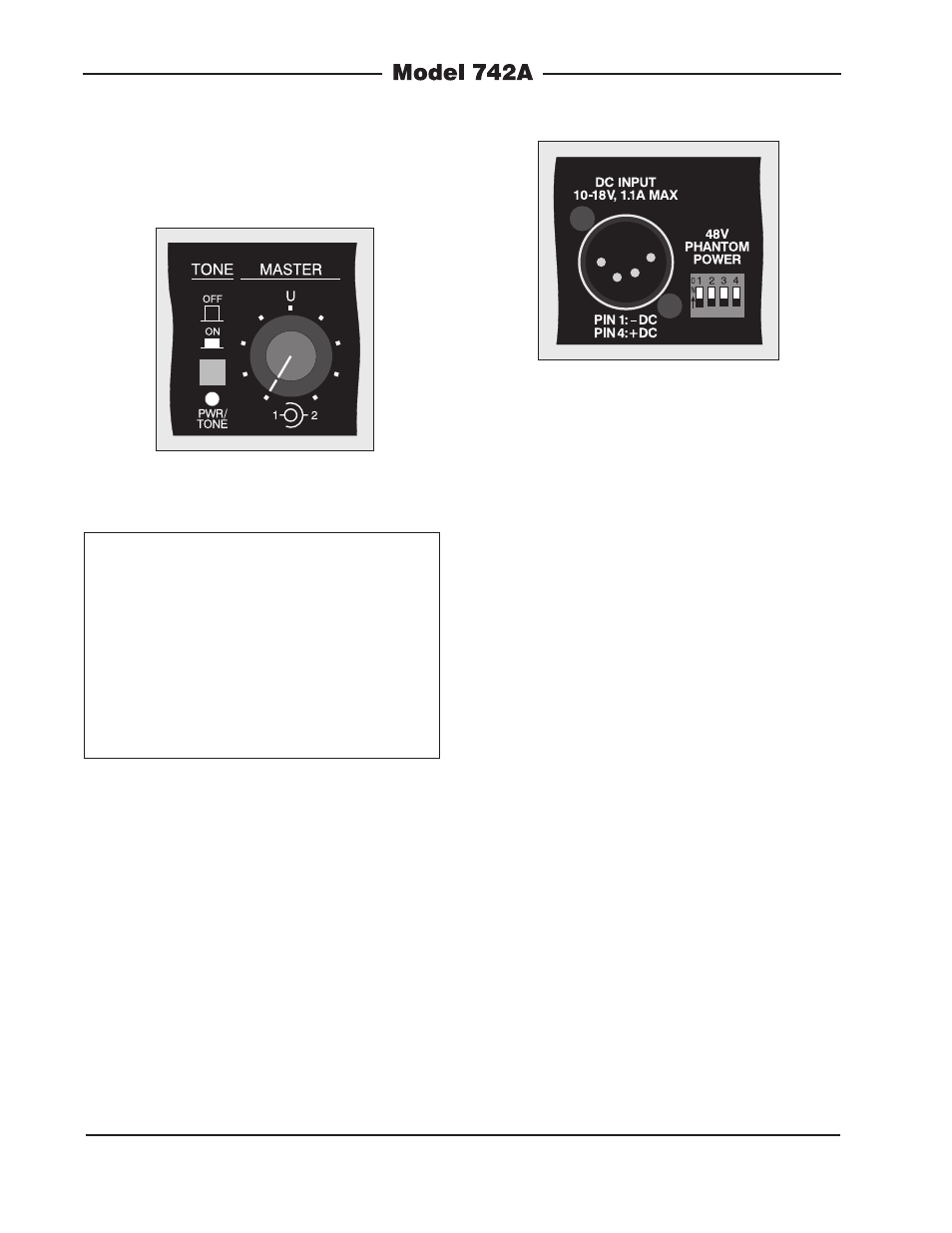
10 for a detailed view.) Prepare a mating
connector (female) so that pin 1 is – DC
and pin 4 is +DC. Pins 2 and 3 are not
used and should remain unconnected.
This connector type and pin-out are
rapidly becoming a broadcast DC power
Figure 10. Detail of back panel showing the DC
input power connector