Operation, Power up, Connecting input signals – Studio Technologies 5110 V.3.2 User Manual
Page 9: Input sensitivity selection
Model 5110 User Guide
Issue 7, October 2014
Studio Technologies, Inc.
Page 9
Model 5110
Mic/Line Input Module
Operation
Power Up
Upon 12 volt DC power being applied to
the Model 5110 the front-panel LEDs will
perform a “walk-through” test, with each
LED lighting briefly in sequence. Then the
LEDs will light in a pattern that represents
the version number of the firmware (em-
bedded software) that is loaded into the
module. Upon completion, the module will
begin normal operation.
Connecting Input Signals
Two 3-pin female XLR connectors are pro-
vided to interface signals with the Model
5110’s mic/line inputs. Signals with a wide
range of nominal levels can be success-
fully connected. For balanced signals pin 2
should be connected to signal + (high) and
pin 3 should be signal – (low). Pin 1 should
be connected to the cable shield.
Unbalanced signals can also be connect-
ed. In most cases signal + (high) should
be connected to pin 2 and common/shield
should be connected to both pins 1 and 3
of the 3-pin male XLR mating connector.
If this connection arrangement results in
hum or noise it’s possible that connecting
signal + (high) to pin 2 and signal com-
mon/shield only to pin 3 may be effective.
Input Sensitivity Selection
Two pushbutton switches are associated
with each mic/line input and are used to
adjust the sensitivity of the input circuitry.
In the line position the Model 5110 will
provide 0 dB of gain which results in unity
input-to-output performance. A connected
signal that has a level of 0 dBu will result
in a 0 dBu signal on the analog output. The
signal level of the digital output will depend
on the version of Model 5110 module. With
a Model 5110S module and an input level
of 0 dBu, the digital output level will be
–24 dBFS. With a Model 5110E module
the digital output level will be –18 dBFS.
Use the up and down pushbutton switches
to adjust the input sensitivity from the
choices of line (0 dB), 15, 30, and 45 dB.
In applications that use a Model 5190
Remote Access Module an expanded gain
range with a step size of 3 dB is possible.
Refer to the Remote Control Section later
in this guide for details.
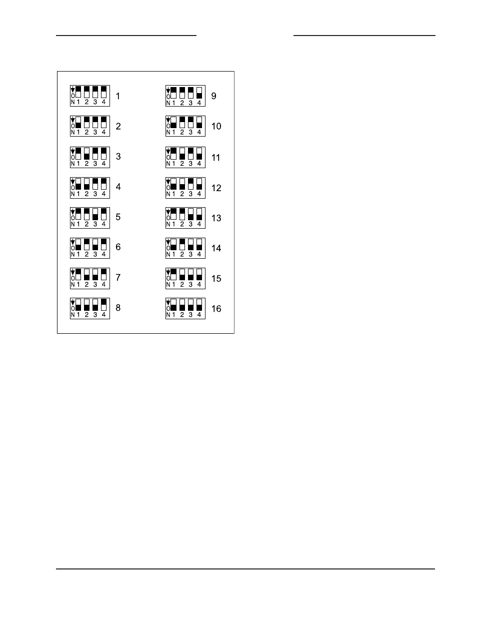
Figure 4. RS-485 Address Settings