Technical notes, Software version display, Cable length – Studio Technologies 41 2013 User Manual
Page 18
Issue 3, November 2013
Model 41 User Guide
Page 18
Studio Technologies, Inc.
to the pin 2 leads on both connectors.
Then connect the meter leads to these two
wires. The meter will indicate the DC cur-
rent being drawn while normal operation
of the connected device(s) takes place. Be
certain to connect the maximum number of
devices that might be powered by the IFB
output. That is, measure the worst-case
condition and ensure that the load is within
the maximum 220 milliamperes output. If
possible, leaving a 5- or 10-percent reserve
margin is a good practice.
Technical Notes
Software Version Display
A special Model 41 power-up sequence
allows the unit’s software version number
to be displayed. This is useful when work-
ing with factory personnel on application
support and troubleshooting situations.
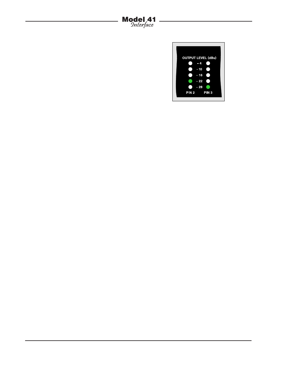
The five LEDs associated with the level
meter for pin 2 are used to display the
major release number with a range of 1
through 5. The five LEDs associated with
the level meter for pin 3 are used to display
the release sub-number which ranges from
1 through 5. Refer to Figure 9 for a detailed
view of the LEDs and the corresponding
software version numbering scheme.
To display the Model 41’s software version
is very simple. From the powered-down
state, press and hold the IFB channel
Circuit Select button. While continuing to
press the button, apply AC mains power to
the unit. The normal power-up sequence
will take place and then, instead of one
status LED being lit, one LED in the Pin 2
column and one LED in the Pin 3 column
will light. These two LEDs represent the
unit’s current software version. The soft-
ware version number will continue to
be displayed until the button is released.
Once the button is released the unit will
begin normal operation.
Note that while it’s easy to determine
which software version is loaded into
the Model 41 a trip back to the factory
is required to update it. The 8-bit micro-
controller that provides the unit’s logic
“horsepower” also includes internal
FLASH memory. This nonvolatile memory
is used to store the operating software
(“firmware”). Re-programming this mem-
ory requires using a specialized program-
ming unit. While not outrageous in price,
it still costs in the range of US$500. The
programmer uses a ribbon cable and
socket to interface with a 6-pin “header”
on the Model 41’s printed circuit board.
And, as you would guess, once connected
reprogramming takes only a matter of
seconds. But unfortunately the program-
mer is not something that would be found
in a typical “field shop” or repair facility.
Cable Length
There are no hard and fast rules defining
the maximum cable length possible when
connecting user devices to the Model 41’s
IFB outputs. The maximum cable length is
directly related to the amount of resistance
Figure 9. Detail of front panel showing the status
LEDs that display software version. In this example,
the software version is 2.1.