Audio monitoring – Studio Technologies 41 2013 User Manual
Page 14
Issue 3, November 2013
Model 41 User Guide
Page 14
Studio Technologies, Inc.
Audio Monitoring
The dual 5-segment LED level meters al-
low a direct observation of the audio levels
present on pins 2 and 3 of the selected IFB
output’s 3-pin XLR connector. In television
broadcast settings, the Pin 2 (left) meter
will typically display the “interrupt” signal
while the Pin 3 (right) meter will display
“program.” A quick glance at the meters
will give an accurate overall indication of
a circuit’s performance.
It’s important to note that the Model 41’s
meters are calibrated differently from the
typical “VU” scale. The level steps were se-
lected to effectively display the IFB output’s
nominal –10 dBu signal level. The ballistics
of the meters are also different, being a
cross between VU and peak. The bottom
four LEDs are green in color and indicate
that signals are in the normal range. The
top LED, yellow in color, lights when signals
are 6 dB or greater above –10 dBu. A cor-
rectly functioning IFB output should find
normal signals lighting the four green LEDs
with the yellow LED lighting only on peaks.
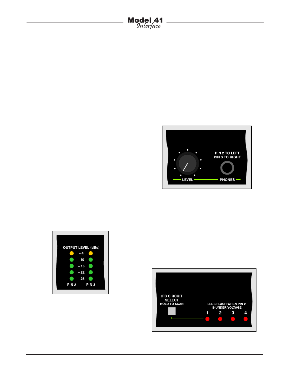
“pro audio” specifications, it’s recom-
mended that high-quality headphones be
used. Pin 2 of the IFB output is the signal
source for the left channel of the head-
phone output. Pin 3 of the IFB output is
the source for the right channel. The rotary
control adjusts the output level of both the
left and right channels. Should it be nec-
essary, there’s no reason why the head-
phone output couldn’t also be used as
a line-level monitor output.
Figure 6. Detail of front panel showing dual
5-segment LED level meters
Figure 7. Detail of front panel showing headphone
section
A pushbutton switch, located on the front
panel, serves two purposes: selecting the
IFB output channel to be monitored and
enabling the auto scan feature. To select
an IFB output channel to be monitored,
press and release the IFB Circuit Select
pushbutton. Each press of the button
will advance the channel to be monitored
The headphone output allows audible
monitoring of the selected IFB output.
The 2-channel (stereo) output is compat-
ible with virtually any pair of stereo head-
phones. As the output circuitry meets
Figure 8. Detail of front panel showing four status
LEDs and associated pushbutton switch