03 ratings, 01 electrical, Consult factory for availability of 2000 a – Southern States CSH User Manual
Page 3: 02 additional, 6 cycles for 245 kv, Rated duty cycle o-15 sec-co-15 sec-co, 03 source supply voltages, Motor voltage 48 vdc or 125 vdc, Auxiliary voltage 120 / 240 vac, 60 hz, 1, Control voltage 48 vdc or 125 vdc
Title: Southern States – CSH & CSH-B
Horizontal Interrupter Style Circuit Switchers
Product Specification Guide
corrosive environment, high altitude installation, etc.) they will be defined
in the quotation request.
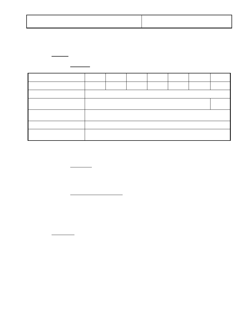
3.03 Ratings
3.03.01 Electrical
Maximum Voltage (kV)
38
48.3
72.5
123
145
170
245
Interrupter/Blade BIL (kV)
350/200 350/250 350/350 550/550 750/650 750/750 900/900
Continuous Current
1200 A, 1600 A or 2000 A*
Maximum System Fault
Rating **
20 kA, 25 kA, 31.5 kA, or 40 kA
20 kA
Rated Short Time (3 sec)
Withstand
40 kA RMS
Fault Closing
10 time 40 kA, 15 time 31.5 kA, 30 time 20 kA
Number of Mechanical
Operations
2000
“
* Consult factory for availability of 2000 A
** Maximum Fault Ratings assume a 3 ohm line to source impedance
3.03.02 Additional
1. Rated Interrupting Time
5 cycles for 170 kV and below
6 cycles for 245 kV
2. Rated Duty Cycle
O-15 sec-CO-15 sec-CO
3.03.03 Source Supply Voltages
Purchaser will supply the following sources for the motor, auxiliary, and
control circuits:
1. Motor Voltage
48 VDC or 125 VDC
2. Auxiliary Voltage
120 / 240 VAC, 60 Hz, 1
∅
3. Control Voltage
48 VDC or 125 VDC
3.04 Interrupter
The circuit switcher shall use SF
6
single gap puffer interrupters. Each interrupter
shall be provided with a color-coded density gauge, an overpressure relief
device, and a gas fill port. Arc assist type interrupters are not acceptable.
Hermetically sealed interrupters are not acceptable due to the inherent dangers
to purchaser’s personnel associated with handling fully pressurized SF
6
devices
during installation and also due to potential hazards encountered during
transportation and offloading.
Page 3 of 9
Publication No.: PSG-803-032615